Pole tube and lift magnet

A pole tube and lift technology, applied in the direction of electromagnets, magnets, electromagnets, etc. with armatures, can solve problems such as thermal overload, deformation of structural components, and inability to design, so as to achieve low manufacturing costs, improve manufacturing quality, and avoid overheating Effect

Active Publication Date: 2015-12-16
ROBERT BOSCH GMBH
View PDF7 Cites 0 Cited by
  • Summary
  • Abstract
  • Description
  • Claims
  • Application Information

AI Technical Summary

Problems solved by technology

[0004] However, it has been shown that in pole tubes with complex structures or thin walls, the energy applied to the pole pieces, intermediate pieces and tubes for melting can cause slight deformation or thermal overloading of the structural components, requiring Finishing still needs to be done between the armature chambers - however, this type of finishing is based on a pole tube that is open on one side, so that for example the lift limiting mechanism that limits the lift of the armature cannot be designed integrally with the tube, but instead must be joined after the fact

Method used


Image

  • Pole tube and lift magnet
  • Pole tube and lift magnet
  • Pole tube and lift magnet

Examples


Embodiment Construction

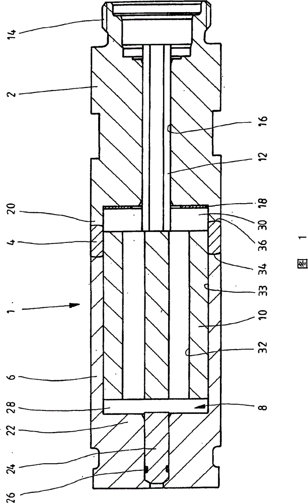
[0018] figure 1 A longitudinal section through a pole tube 1 of a simple-acting lift magnet in a pressure-tight design is shown. The pole tube essentially consists of a pole piece 2 , an intermediate piece 4 and a tube piece 6 , which are connected to one another by a thermal joining method, in the exemplary embodiment shown by capacitive discharge welding (KES). These three components together form the armature cavity 8 . In this cavity, the armature 10 of the lift magnet is guided axially displaceably. The plunger 12 is fixedly or detachably mounted on the armature 10 . This plunger passes through the pole piece 2 in the axial direction and serves to actuate the control slide of the valve to be actuated by the lift magnet.

[0019] pole shoe 2 in it's in figure 1 The right-hand end section shown in has a central thread 14 . With this central thread, the pole piece can be screwed into the valve bore of the valve housing, so that the operative connection of the plunger 12...


PUM


Abstract

The present invention discloses a diode (1) and a lift magnet having a diode, having a middleware (4), the middleware is connected to the pole shoe (2) and the tube (6). Together, they form a housing cavity (8) of the armature (10) for the lift magnet. According to the present invention, the geometry of the end face area of the middleware and pipe fittings and pole shoees connected by welding is so selected, i.e., in the case of considering the melting point of the material employed, the resistance of the joint is substantially the same in the joint area, so that the amount of thermal input entering the two joints during resistance welding is about the same. Wherein, the joint consisting of a material with a smaller resistance than the resistance has a smaller cross-section (46, 64) than another joint composed of a material with a larger resistance.

Description

technical field [0001] The invention relates to a pole tube, in particular for a lift magnet of a hydraulic valve, and to a lift magnet with a pole tube of this type. Background technique [0002] Such a pole tube is known from DE 10243165 A1 and is a component part of a pressure-tight lifting magnet. In addition to the pole tube, the lift magnet has a coil for actuating an armature guided in axial movement in the cavity of the pole tube, wherein the coil surrounds the pole tube. The pole tube essentially consists of a pole shoe, which is screwed into the valve housing via a central thread, a non-magnetic intermediate piece and a pipe piece connected to this intermediate piece. This tube is closed at the end on the side facing away from the pole piece by means of a structural part serving as lift limiting means. This lift limiting mechanism can also be integrated into the pole piece. The pole piece, the intermediate piece, the tube and the lift limiting mechanism define a...

Claims


Application Information

Patent Timeline
Patent Type & Authority Patents(China)
IPC IPC(8): H01F7/127B23K11/14B23K11/20H01F7/08
CPCB23K11/26H01F7/127H01F2007/085B23K2103/05B23K2103/18B23K2103/22Y10T29/49075
Inventor J·格伦C·吉格里克R·谢姆普
Owner ROBERT BOSCH GMBH
Why Eureka
Try Eureka