Thin paper winding apparatus having reverse poking mechanism

A reverse, paper roll technology, applied in the direction of winding strips, thin material handling, transportation and packaging, etc., can solve the problems of thin paper breakage, insufficient speed difference, and inability to absorb thin paper.

Inactive Publication Date: 2009-03-04
CHAN LI MACHINERY
View PDF1 Cites 4 Cited by
  • Summary
  • Abstract
  • Description
  • Claims
  • Application Information

AI Technical Summary

Problems solved by technology

[0004] However, in the above-mentioned existing tissue paper winding device, it must be noted that the rotation speed of the rotating rod cannot be the same as the rotation speed of the winding wheel, so as to cause a speed difference and cause the tissue paper to break, and if the tissue paper is made of high toughness material When it is made, if the speed difference between the rotating rod and the winding wheel is not large enough, it will not cause the thin paper to break
[0005] Furthermore, the rotation direction of the rotating rod in the existing tissue paper winding device is the same as the transmission direction of the tissue paper, and it cannot absorb the tissue paper, which does not help the tissue paper to be wound on the paper tube

Method used


Image

  • Thin paper winding apparatus having reverse poking mechanism
  • Thin paper winding apparatus having reverse poking mechanism
  • Thin paper winding apparatus having reverse poking mechanism

Examples


Embodiment Construction

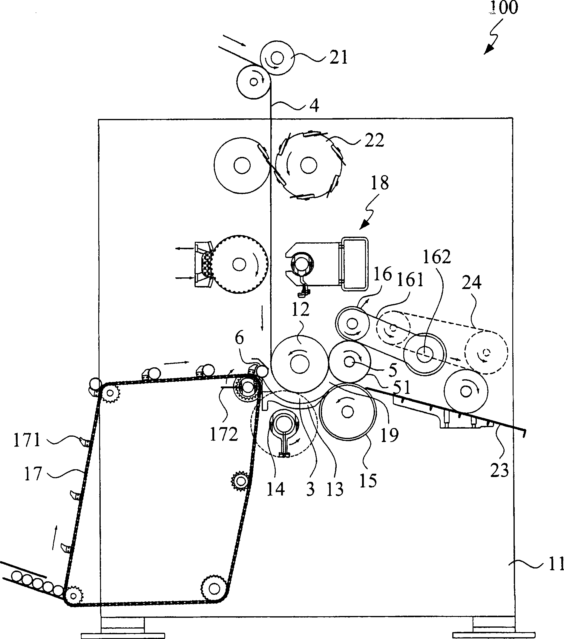
[0073] refer to figure 1 As shown, the first embodiment 100 of the tissue paper winding device with reverse dial-off mechanism of the present invention includes a base 11, a winding wheel 12, and a plurality of guide plates 13 (only one can be seen in the side view) , a reverse pull-off mechanism 14, a roll wheel 15, a riding wheel 16, a paper tube conveying device 17, a gluing mechanism 18, a pair of pinch wheels 21, a punching device 22, an inclined passage 23 and One compresses the conveyor belt 24.

[0074] The guide plate 13 is arranged at a position adjacent to the lower side of the winding wheel 12 and forms a channel 3 with the winding wheel 12 . A winding area 19 is formed between the upper winding wheel 12 , the lower winding wheel 15 and the riding wheel 16 . A thin paper 4 with a predetermined thickness and width is conveyed via the pinch wheel 21, and a row of holes is punched at a predetermined distance through the punching device 22, and then a tail glue and a...


PUM


Abstract

The invention relates to a flimsy winding device provided with a reverse pulling-apart mechanism, which comprises an upper roller and the reverse pulling-apart mechanism. Flimsy is close attached to the roller surface of the lower half of the upper roller and winds a paper tube along a preset transfer direction; the reverse pulling-apart mechanism is arranged below the upper roller and comprises a rotating shaft, at least a shifter lever and a drive mechanism; the shifter lever is arranged on the outer torus of the rotating shaft and comprises a rotating shaft connection end and a press touching end which extends from the outer torus of the rotating shaft in a protruding manner; the drive mechanism is used for driving the shifter lever to rotate around the rotating shaft; the rotation direction of the shifter lever is opposite to the transfer direction of the flimsy. When being driven to rotate to the truncation position by the drive mechanism, the press touching end of the shifter lever just leads the flimsy which passes through the space between the upper roller and the press touching end to be clamped and provides a pulling-apart force along the opposite direction to enable the flimsy to be pulled apart.

Description

technical field [0001] The invention relates to the design of a thin paper winding device, in particular to a thin paper winding device with a reverse pull-off mechanism. Background technique [0002] The paper tube of a general thin paper winding device is delivered to an upper roll by a conveyor, then pushed into a guide plate channel by a push rod, and then reaches a winding area, where the thin paper is wound on the paper tube. Paper becomes a roll of paper, such as a roll of toilet paper, etc., as disclosed in U.S. Patent No. 5,769,352. The rotating rod, that is, use a rotating rod whose rotating speed is slightly slower than the rotating speed of the winding wheel to break off the thin paper, and the rotating direction of this rotating rod is the same as the transmission direction of the thin paper. Or, some manufacturers also control the rotation speed of a rotating rod so that the relative speed is faster than the speed difference of the winding wheel to cause the t...

Claims


Application Information

Patent Timeline
Patent Type & Authority Applications(China)
IPC IPC(8): B65H19/22B65H19/26B65H19/28
Inventor 蔡东义
Owner CHAN LI MACHINERY
Why Eureka
Try Eureka