Photographing recognition system of clamp assembling machine

A technology of identification system and assembly machine, applied in the field of machinery, can solve the problems of easy clamping, low efficiency, and inability to place the robot smoothly, and achieve the effect of automation

Inactive Publication Date: 2018-10-16
JIANGSU BVM INTELLIGENT TECH
View PDF0 Cites 2 Cited by
  • Summary
  • Abstract
  • Description
  • Claims
  • Application Information

AI Technical Summary

Problems solved by technology

In the prior art of the clamp assembly machine, the feeding method adopts the combination of vibrating plate and vibrating conveyor, which is noisy and cannot discharge the material; the detection of the attitude state of the outer clamp clamp is to use the camera recognition and flipping mechanism, which is inefficient; and the manipulator for the outer clamp When the hoop is grasped and transferred to the assembly turntable, the manipulator is easy to clamp the nut head of the hoop, which makes the manipulator unable to grip the outer hoop and cannot be placed on the platform when the inner hoop is preloaded smoothly; The hoop and the outer hoop are deformed when they are assembled and pressed together. Although the upper pressing plate mechanism is installed, the efficiency is low. Defects make improvements

Method used


Image

  • Photographing recognition system of clamp assembling machine
  • Photographing recognition system of clamp assembling machine
  • Photographing recognition system of clamp assembling machine

Examples


Embodiment Construction

[0027] The present invention will now be further described in detail in conjunction with the accompanying drawings and embodiments. These drawings are all simplified schematic diagrams, only illustrating the basic structure of the present invention in a schematic manner, so it only shows the composition related to the present invention.

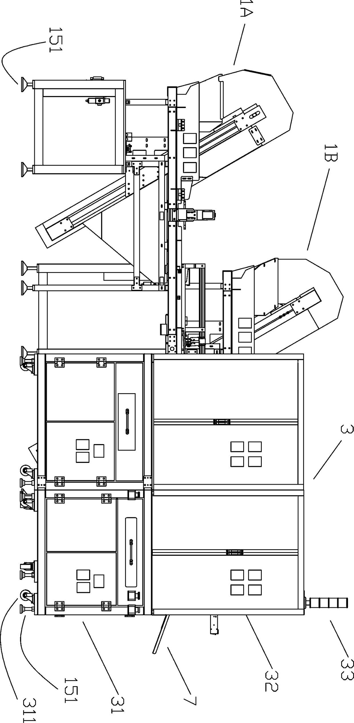
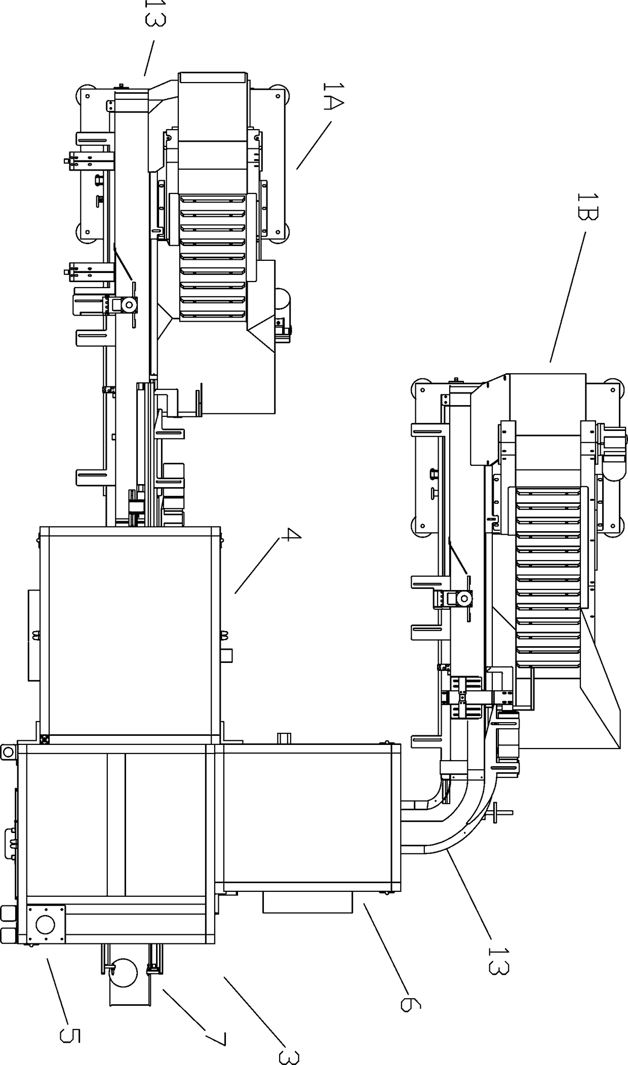
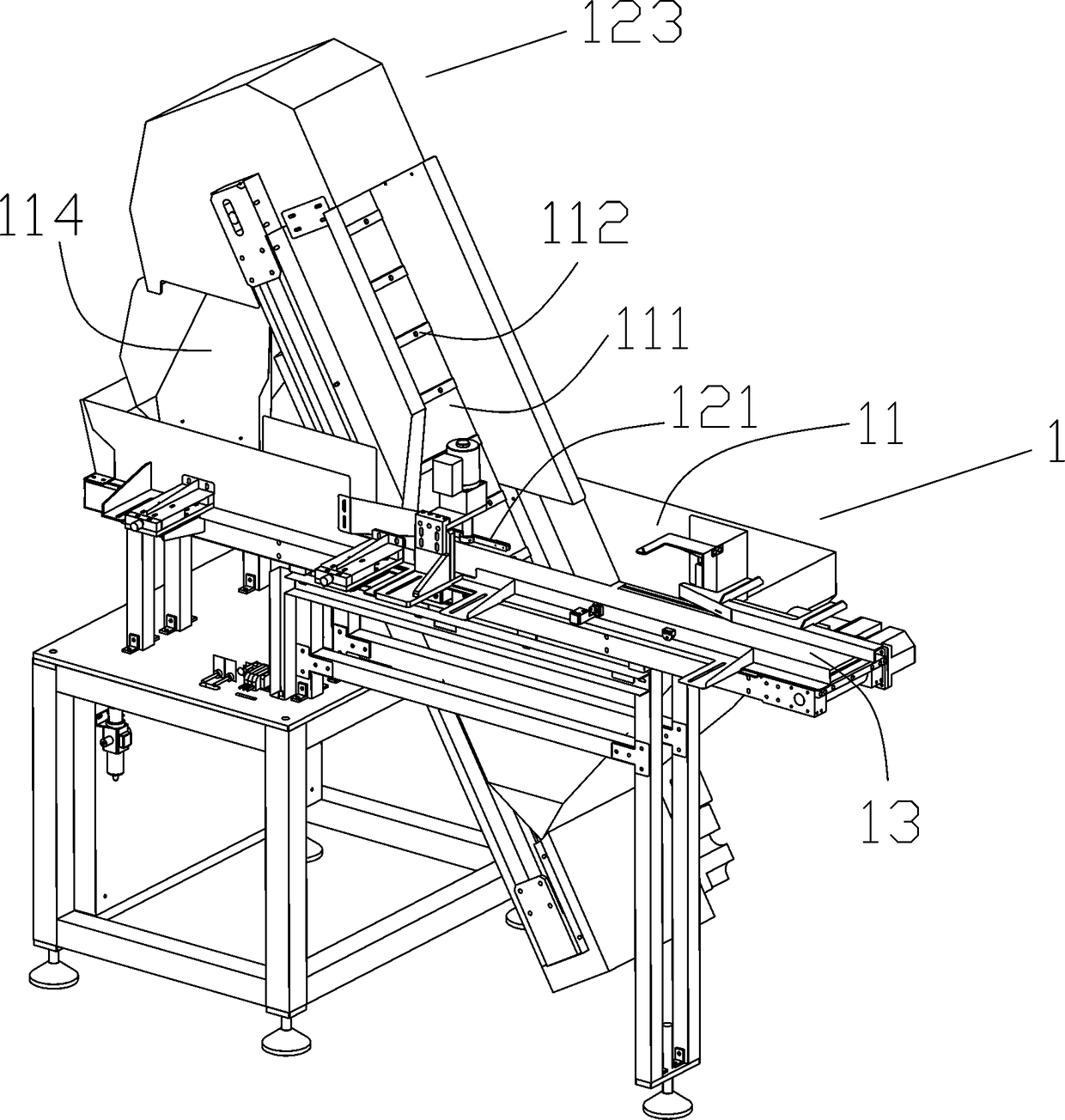
[0028] Such as Figure 1~Figure 9 As shown, a hoop assembly machine includes a feeding mechanism 1, the feeding mechanism 1 is divided into an inner hoop feeding mechanism 1B and an outer hoop feeding mechanism 1A, a transmission mechanism 13 connected with the feeding mechanism 1, and a transmission mechanism 13 is provided with a blocking mechanism 12 and a photographic identification system 14 in sequence, and the feeding mechanism 1 is connected with the operating mechanism 3 through a transmission mechanism 13;

[0029] In a preferred embodiment of the present invention, as Figure 1~Figure 4 As shown, the feeding mechanism 1 includes a...


PUM


Abstract

The invention discloses a photographing recognition system of a clamp assembling machine. The photographing recognition system is arranged on a conveying mechanism of the clamp assembling machine. A conveying table for conveying materials is arranged in the conveying mechanism. The photographing recognition system is arranged above the conveying table and comprises a photographing device arrangedabove the conveying table and a material removing device which is arranged above the conveying table and located below the photographing device. The photographing recognition system comprises the photographing device and the material removing device electrically connected with the photographing device. Once it is found that fastening screws on clamps are located below the clamps, the clamps are removed to return into a hopper, and finally, clamps with upward fastening screws are sequentially conveyed to the next assembling procedure. The photographing recognition system of the clamp assemblingmachine is provided and is simple in structure and more accurate and rapid in material screening.

Description

technical field [0001] The invention relates to the field of machinery, in particular to a photo identification system of a hoop assembly machine. Background technique [0002] The clamp is a connecting device for connecting grooved pipe fittings, valves and pipeline fittings. It is used to tighten the coupling between the quick joints. Generally, the clamp is divided into an inner clamp and an outer clamp. Through the clamp group The machine presses and assembles the inner and outer clamps. In the prior art of the clamp assembly machine, the feeding method adopts the combination of vibrating plate and vibrating conveyor, which is noisy and cannot discharge the material; the detection of the attitude state of the outer clamp clamp is to use the camera recognition and flipping mechanism, which is inefficient; and the manipulator for the outer clamp When the hoop is grasped and transferred to the assembly turntable, the manipulator is easy to clamp the nut head of the hoop, w...

Claims


Application Information

Patent Timeline
IPC IPC(8): B23P19/02
CPCB23P19/001B23P19/02
Inventor 李相鹏
Owner JIANGSU BVM INTELLIGENT TECH
Why Eureka
Try Eureka