Method for detecting receive signal of multi-input multi-output system and detector thereof

A technology for receiving signals and detecting methods, which is applied in the field of detectors and can solve problems such as poor performance

Inactive Publication Date: 2009-03-04
ZTE CORP
0 Cites 11 Cited by

AI-Extracted Technical Summary

Problems solved by technology

Although the SQRD detection method reduces the detection complexit...

Abstract

The invention provides a detection method and a detector of a received signal in a multi-input multi-output system, The method comprises the steps: a received signal rM and an estimated channel matrix H M multiplied by N are carried out with conversion, a converted received signal is obtained as the right formula (I) and a converted channel matrix is obtained as the right formula (II); and according to the converted received signal r M+N and a converted channel matrix shown in the right formula (III), a QR factorization method is adopted to detect and restore a sending signal. The detector comprises a channel conversation module and a QR factorization detection module, wherein, the channel conversation module is used for converting the channel matrix H M multiplied by N and the received signal rM, and the QR factorization detection module is used for detecting and restoring the sending signal by the QR factorization method according to the converted received signal rM+N and the converted channel matrix shown in the right formula (III). The invention is equivalent to the original used MMSE-SIC detection method, but the complexity is obviously reduced.

Application Domain

Baseband system detailsTransmission monitoring +1

Technology Topic

ChemistryMulti output +2

Image

  • Method for detecting receive signal of multi-input multi-output system and detector thereof
  • Method for detecting receive signal of multi-input multi-output system and detector thereof
  • Method for detecting receive signal of multi-input multi-output system and detector thereof

Examples

  • Experimental program(1)

Example Embodiment

[0033] The technical solutions of the present invention will be described in more detail below with reference to the accompanying drawings and embodiments.
[0034] The present invention provides a method and detector for detecting a received signal in a MIMO system, and the method and detector are applicable to other communication systems that can be modeled as MIMO.
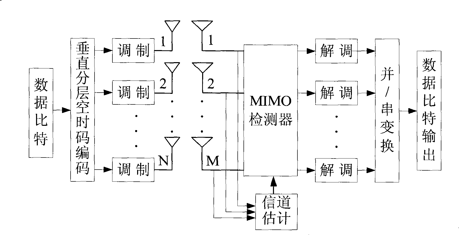
[0035] figure 1 It is the basic principle block diagram of the MIMO system, the number of transmit antennas is N, and the number of receive antennas is M. At the transmitting end, the high-speed data bit stream is converted into N low-speed data streams through serial-parallel conversion, and each data bit stream is modulated and transmitted from different antennas at the same time; after the wireless channel fades, the signals from different transmitting antennas are superimposed with noise. After being received by multiple antennas at the same time, the MIMO detector uses the channel state information generated by the channel estimation module to recover the transmitted signal from the received signal, and sends it to the demodulation module; after demodulation, the data bit stream of the transmitting end is obtained through parallel/serial conversion . Channel coding is not considered in this system, and the baseband signal output signal of this system can be expressed as: r M =H MxN ·t N +n M.
[0036] where r M is the received signal vector of M receiving antennas, H MxN is the channel matrix between M receiving antennas and N transmitting antennas, t N is the signal vector of N transmitting antennas, n M is the additive noise vector for M receiving antennas. Before performing the MIMO detection process, the channel estimator firstly obtains the estimated value of the channel matrix, which is assumed to be an ideal channel estimation here.
[0037] The weighting matrix under the MMSE criterion is: G NxM = ( H NxM H H MxN + σ n 2 I N ) NxN - 1 H NxM H ; H H is the conjugate transpose of the channel matrix H, is the noise power of each receiving antenna, I N is an N*N identity matrix. The estimated value of the transmitted signal is:
[0038] t ′ N = G NxM · r M = ( H NxM H H MxN + σ n 2 I N ) NxN - 1 H NxM H · r M
[0039] The detection method of the received signal in the MIMO system provided by the invention comprises the following steps:
[0040] A. After the receiving end receives the signal through the receiving antenna, the channel estimation module uses the prior art to estimate the channel matrix according to the pilot frequency of the received signal; the channel matrix estimated by the pilot frequency is H M×N , where N is the number of transmit antennas and M is the number of receive antennas.
[0041] B. The channel conversion module compares the signal r received by the receiver M and the channel matrix H M×N Transform to get the transformed received signal r M+N and the transformed channel matrix H (M+N)xN as follows:
[0042] r ‾ M + N = r M 0 N = H ‾ ( M + N ) xN · t N + n M 0 N
[0043] H ‾ ( M + N ) xN = H MxN σ n I NxN ( M + N ) xN - - - ( 1 )
[0044] where σ n is the noise vector.
[0045] C. The matrix decomposition sub-module in the QR decomposition detection module pairs the transformed channel matrix H (M+N)xN Carry out QR decomposition, the method of decomposition is the same as the prior art, obtains orthogonal matrix Q and upper triangular matrix R as follows:
[0046] H ‾ ( M + N ) xN = H MxN σ n I NxN ( M + N ) xN = Q ‾ ( M + N ) xN · R ‾ NxN = Q 1 MxN Q 2 NxN · R ‾ NxN = Q 1 MxN · R ‾ NxN Q 2 NxN · R ‾ NxN ( M + N ) xN - - - ( 2 )
[0047] From formula (2), the following two relations can be obtained:
[0048] σ n I NxN = Q 2 NxN R ‾ NxN ⇒ R ‾ NxN - 1 = σ n - 1 Q 2 NxN - - - ( 3 )
[0049] Multiply both sides of equation (2) by the left Get the following relation:
[0050] Q ‾ Nx ( M + N ) H H ‾ ( M + N ) xN = R ‾ NxN
[0051] ⇒ Q 1 NxM H Q 2 NxN H H MxN σ n I NxN = Q 1 NxM H H MxN + σ n Q 2 NxN H = R ‾ NxN - - - ( 4 )
[0052] ⇒ Q 1 NxM H H MxN = R ‾ NxN - σ n Q 2 NxN H
[0053] D. The signal detection sub-module in the QR decomposition detection module uses the sorting QR decomposition method to detect and restore the transmitted signal; of course, in practical applications, any QR decomposition method can be used to detect and restore.
[0054] It can be obtained from the previous formula that for the transformed received signal, the weighting matrix is Q H; that is, the received signal r M+N Multiply left by Q H , the estimated value of the transmitted signal is:
[0055] t ′ N = Q ‾ Nx ( M + N ) H · r ‾ M + N
[0056] because:
[0057] Q ‾ ( M + N ) xN = Q 1 MxN Q 2 NxN ⇒ Q ‾ Nx ( M + N ) H = Q 1 NxM H Q 2 NxN H
[0058] r ‾ M + N = r M 0
[0059] F:
[0060] t ′ N = Q 1 NxM H · r M - - - ( 5 )
[0061] will r M =H MxN ·t N +n M Substitute into equation (5) to get the estimated value of the transmitted signal:
[0062] t ′ N = Q 1 NxM H · r M = Q 1 NxM H · [ H MxN · t N + n M ] = Q 1 NxM H · H MxN · t N + Q 1 NxM H · n M - - - ( 6 )
[0063] Substituting equation (4) into equation (6) can get:
[0064] t ′ N = [ R ‾ NxN - σ n Q 2 NxN H ] · t N + Q 1 NxM H · n M
[0065] t ′ N = R ‾ NxN · t N + Q 1 NxM H · n M - σ n Q 2 NxN H · t N - - - ( 7 )
[0066] t ′ N = R ‾ NxN · t N - σ n 2 R ‾ NxN - H t N + Q 1 N × M H · n M
[0067] The second term of equation (7) contains a lower triangular matrix R NxN -H , this item is the interference item that is not eliminated after passing SIC, that is, after adopting the MMSE criterion, the interference of the upper layer to the lower layer cannot be completely removed, and the detection method of the present invention takes a compromise between noise amplification and interference elimination. The estimation errors of different layers correspond to the diagonal elements of the error covariance matrix, and the estimation errors after interference removal are:
[0068] Φ ( k , k ) = σ n 2 / | r ‾ k , k | 2
[0069] of which | r k,k | 2 is the square of the modulus of the main diagonal elements of the upper triangular matrix R obtained by QR decomposition.
[0070] To sum up, the complexity of the detection method of the present invention is much smaller than that of the MMSE-SIC detection method, and the detection performance can be judged from the experimental data, image 3 Shown is that the transmitting antenna and the receiving antenna are both 2, adopt QPSK (Quadrature Phase Shift Keying) modulation mode, when there is no channel coding, the simulation result of the existing detection method and the detection method of the present invention; Figure 4 Shown is that both the transmitting antenna and the receiving antenna are 2, using 16QAM (Quadrature Amplitude Modulation) modulation mode, when there is no channel coding, the simulation results of the existing detection method and the detection method of the present invention; it can be seen that image 3 Among them, the performance of the detection method of the present invention is better than the existing sorting QR decomposition detection method, and the performance is comparable to the existing MMSE-SIC detection method; Figure 4 The performance of the detection method of the present invention is also better than that of the existing sorting QR decomposition detection method, and the performance is basically equivalent to the performance of the existing MMSE-SIC detection method.
[0071] The present invention also provides a detector in a MIMO system, including a channel transformation module and a QR decomposition detection module;
[0072] The channel transformation module is used to receive the channel matrix H estimated by the channel estimation module M×N , and the channel matrix H M×N and the signal r received by the receiver M Transform to get the transformed received signal r M+N and the transformed channel matrix H (M+N)xN as follows:
[0073] r ‾ M + N = r M 0 N = H ‾ ( M + N ) xN · t N + n M 0 N
[0074] H ‾ ( M + N ) xN = H MxN σ n I NxN ( M + N ) xN
[0075] The QR decomposition detection module is used for receiving the signal according to the transformed r M+N and the transformed channel matrix H (M+N)xN , adopt QR decomposition to detect and restore the transmitted signal, including matrix decomposition sub-module and signal detection sub-module;
[0076] The matrix decomposition sub-module is used to receive the transformed channel matrix H (M+N)xN And perform QR decomposition on it to obtain an orthogonal matrix Q and an upper triangular matrix R such as formula (2);
[0077] The signal detection sub-module is used to detect and restore the transmitted signal according to the orthogonal matrix Q and the upper triangular matrix R according to the sorting QR decomposition method, obtain the estimated value of the transmitted signal as shown in equation (7), and output it to the modulator.
[0078] Of course, the present invention can also have other various embodiments, without departing from the spirit and essence of the present invention, those skilled in the art can make various corresponding changes and deformations according to the present invention, but these corresponding Changes and deformations should belong to the protection scope of the appended claims of the present invention.

PUM

no PUM

Description & Claims & Application Information

We can also present the details of the Description, Claims and Application information to help users get a comprehensive understanding of the technical details of the patent, such as background art, summary of invention, brief description of drawings, description of embodiments, and other original content. On the other hand, users can also determine the specific scope of protection of the technology through the list of claims; as well as understand the changes in the life cycle of the technology with the presentation of the patent timeline. Login to view more.
Why Eureka
Try Eureka