Supercharge Your Innovation With Domain-Expert AI Agents!

Sealed flange joint for high pressure and high purity gas channels

A technology for sealing flanges and fluid passages. It is used in flange connections, pipe joints, and pipe connection arrangements. It can solve the problem that metal O-rings are not suitable for detachable connections.

Inactive Publication Date: 2009-03-04
LUXEMBOURG PATENT CO SA
View PDF0 Cites 1 Cited by
  • Summary
  • Abstract
  • Description
  • Claims
  • Application Information

AI Technical Summary

Problems solved by technology

However, if the metal o-rings are subjected to high pressure, the metal o-rings will leave indentations in the sealing surfaces with which they come into contact, making metal o-rings unsuitable for use in a detachable connection

Method used


Image

  • Sealed flange joint for high pressure and high purity gas channels
  • Sealed flange joint for high pressure and high purity gas channels
  • Sealed flange joint for high pressure and high purity gas channels

Examples


Embodiment Construction

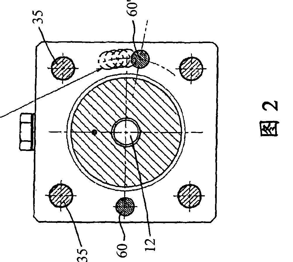
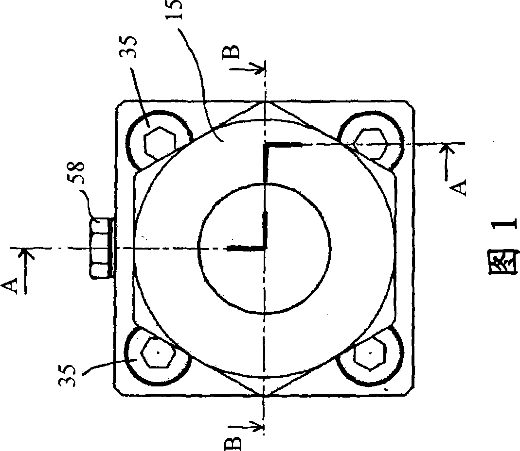
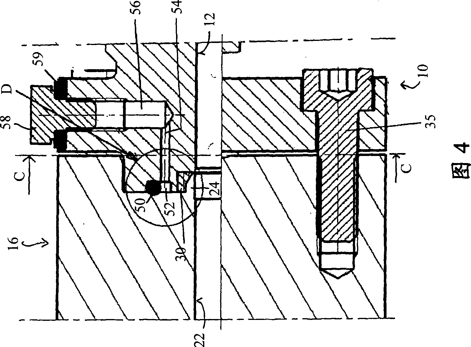
[0034] The figures show a preferred embodiment of a sealed flange joint according to the invention. As will be shown below, a sealed flange joint involves the fitting of a pair of flanges in a sealed manner. This flange joint design can be used as a variety of sealed connections in fluid (especially gas) passages and any fluid / gas containment, processing or distribution systems, such as between gas cylinder valve ports and delivery pipes. This type of flanged joint is especially suitable for applications using ultra-pure, highly corrosive, and high-pressure gases.

[0035]Referring now to FIG. 3 , there is shown a first flange 10 having a first gas passage 12 and a gas collector front cavity 14 . This first flange 10 can be arranged, for example, at the end of the conveying pipe 15 . Reference numeral 16 generally designates a second flange, the two flanges 10 and 16 being detachably secured to each other as will be further explained below. Such a second flange structure ma...


PUM


Abstract

A sealed flange joint for high pressure and / or high purity fluid channels com- prises a first flange (10) with a first fluid channel (12) and a cylindrical front cavity (14). The front cavity (14) is axially delimited by a ground surface (18) and radially by a peripheral surface (20). The first fluid channel (12) passes axially through the first flange (10) to open into the ground surface (18). A polymer seal ring (30) has a radial outer surface (32) and a radial inner surface (34), and is fitted into the cylindrical front cavity (14) so that its radial outer surface (32) engages the peripheral surface (20) of the front cavity. A second flange (16) is removably fixed onto the first flange (10), and has a second fluid channel (22) in axial continuation of the first fluid channel (12). The second flange (16) has an axially protruding cylindrical front nipple (24) with a conical head (26), the second fluid channel (22) axially opening into an end surface (28) of the conical head (26). The conical head (26) engages the radial inner surface (34) of the seal ring (30) to radially press the latter with its radial outer surface (32) against the peripheral surface (20) of the front cavity (14).

Description

technical field [0001] The present invention generally relates to a sealing flange joint for a fluid channel, in particular to a sealing flange joint for a high pressure and / or high purity gas channel. Background technique [0002] The widespread use of specialty gases, and the ever-increasing purity requirements of some modern industries, have created the need for increasingly complex delivery systems of the highest quality and integrity. [0003] For example, in the semiconductor / chip fabrication industry, high quality gas channels are required since any impurities in the gas may adversely affect the electrical characteristics of the device and may greatly reduce manufacturing yield. Most often, these gases are also very reactive, corrosive, and / or toxic. [0004] Therefore, the containment, processing and delivery of ultrapure gases especially require suitable installations as well as high-quality equipment. In these systems, the quality of joints and seals is especiall...

Claims


Application Information

Patent Timeline
Patent Type & Authority Applications(China)
IPC IPC(8): F16L23/032
CPCF16L23/22F16L23/032F16L2201/30F16L47/14
Inventor 保罗·穆佐保罗·克雷默
Owner LUXEMBOURG PATENT CO SA
Features
  • R&D
  • Intellectual Property
  • Life Sciences
  • Materials
  • Tech Scout
  • Unparalleled Data Quality
  • Higher Quality Content
  • 60% Fewer Hallucinations
Learn More