Non-contact automobile gear indicator

A non-contact, indicator technology, applied in the direction of components with teeth, belts/chains/gears, mechanical equipment, etc., can solve the problem that the automobile gear indicator cannot be practical, and it is impossible to use the gear indicator.

Inactive Publication Date: 2009-03-11
上海今泉科技发展有限公司
View PDF0 Cites 0 Cited by
  • Summary
  • Abstract
  • Description
  • Claims
  • Application Information

AI Technical Summary

Problems solved by technology

[0002] In the prior art, the gear position indicator at home and abroad is realized by mechanical transmission driving the contact switch. Due to the influence of the life of the switch and the influence of mechanical wear, it is impossible to use the gear indicator as a regular means.
[0003] Due to the above reasons, the automotive gear position indicator cannot be practically used in automotive electronic equipment.

Method used


Image

  • Non-contact automobile gear indicator

Examples


Embodiment Construction

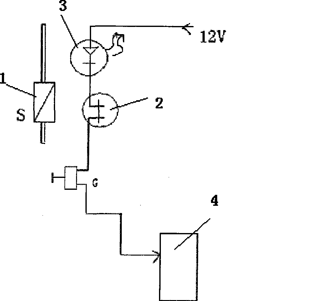
[0009] Below in conjunction with accompanying drawing and specific embodiment the present invention is described in further detail:

[0010] Depend on figure 1 Visible: the present invention comprises: a magnet 1 that is rigidly connected with the automobile gear control lever, a reed switch controller 2 that is fixed on the automobile, is positioned relative to the magnet 1 and is adjusted to the state that can control the gear position, and is placed on the A luminous tube indicating circuit 3 connected to the reed switch controller 2 and a processor 4 connected to the reed switch controller 2 and the luminescent tube indicating circuit 3 within the driver's line of sight;

[0011] Described processor 4 can be intelligent single-chip microcomputer identification circuit;

[0012] The present invention utilizes the reed switch control circuit, the luminescent tube indicating circuit, and the intelligent single-chip microcomputer identification circuit to convert the position...


PUM


Abstract

The invention relates to a non-contact typed automobile gear position indicator, comprising a magnet (1) which is rigidly connected with an automobile gear operation rod, a reed switch controller (2) which is fixed on the automobile, arranged at the position corresponding to the magnet (1) and can be adjusted to control the gear state, a luminescence pipe indicator circuit (3) which is arranged in the sight range of the driver and connected with the reed switch controller (2), and a processor (4) which is connected with the reed switch controller (2) and the luminescence pipe indicator circuit (3); the indicator has the beneficial effects that magnetic force is used as the non-contact typed switch, the mechanical switch is omitted, zero abrasion is realized due to no contact, thereby leading the automobile gear position indicator to run safely and reliably for a long time.

Description

technical field [0001] The invention relates to a car gear, in particular to a gear position indicator of the car gear. Background technique [0002] In the prior art, the gear position indicator at home and abroad is realized by mechanical transmission driving the contact switch. Due to the impact of switch life and mechanical wear, it is impossible to use the gear indicator as a regular means. [0003] Due to the above reasons, the automotive gear position indicator cannot be practically used in automotive electronic equipment. Contents of the invention [0004] The technical problem to be solved by the present invention is to provide a non-contact automotive gear position indicator, which aims to solve the above-mentioned problems. [0005] In order to solve the above technical problems, the present invention is achieved through the following technical solutions: [0006] The present invention includes: a magnet rigidly connected with the gear control lever of the car...

Claims


Application Information

Patent Timeline
Patent Type & Authority Applications(China)
IPC IPC(8): F16H63/42
Inventor 时维新郑晟
Owner 上海今泉科技发展有限公司
Why Eureka
Try Eureka