Joint for corrugated tube

A technology for corrugated pipes and pipes, applied in the direction of pipes/pipe joints/fittings, hose connection devices, mechanical equipment, etc., can solve problems such as leakage, damage to the reliability of flexible pipe connections, and difficulty in handling

Active Publication Date: 2009-03-11
HITACHI METALS LTD
View PDF2 Cites 10 Cited by
  • Summary
  • Abstract
  • Description
  • Claims
  • Application Information

AI Technical Summary

Problems solved by technology

Moreover, it is difficult for the operator to distinguish the feel of the bellows passing through the inner circumference of the ring-shaped sealing material and the feel of the stopper.
Therefore, when the corrugated pipe is not actually inserted into the predetermined position of the joint, the construction will be completed and the construction will be terminated, causing problems such as leakage.
[0010] In addition, according to the flexible pipe joint of Patent Document 3, the gasket is compressed in the expanding radial direction by the outer peripheral surface of the flexible pipe before the front end of the flexible pipe abuts against the back end of the gasket, so it may be difficult to make the gasket radially expanded by the operator's pipe insertion force. The gasket moves to the inside of the joint body or the gasket moves before the front end of the flexible pipe reaches the back end of the gasket, thereby damaging the connection reliability of the flexible pipe

Method used


Image

  • Joint for corrugated tube
  • Joint for corrugated tube
  • Joint for corrugated tube

Examples


no. 1 approach 〕

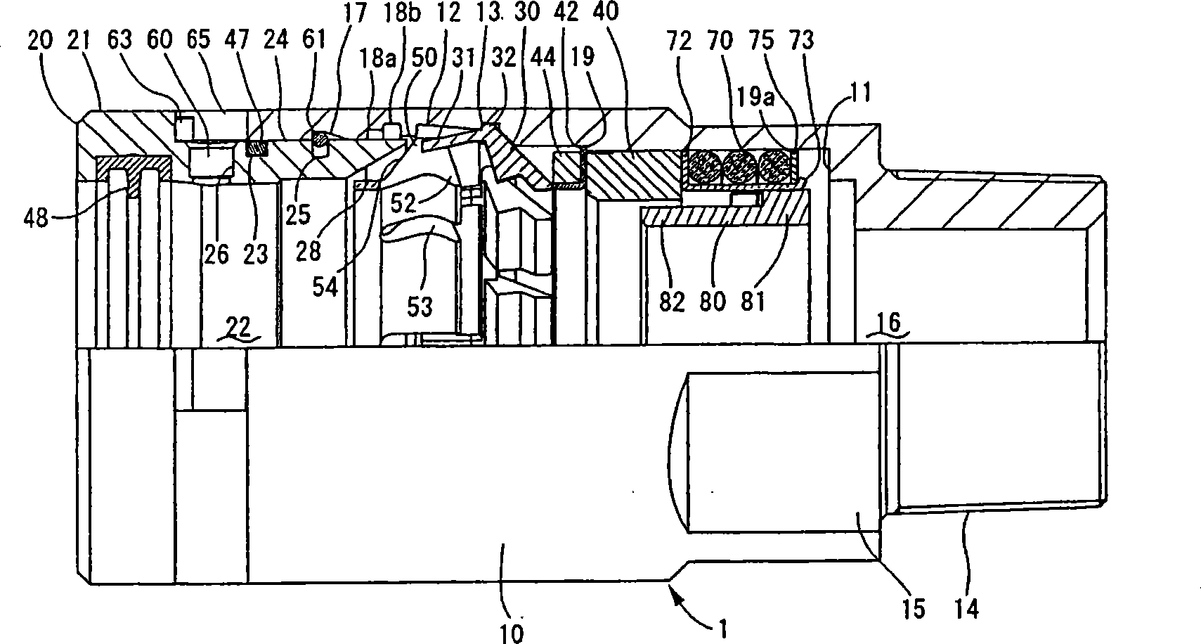
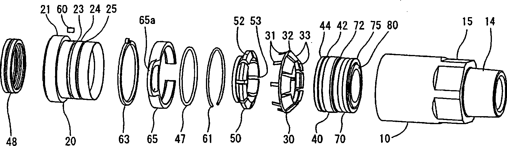
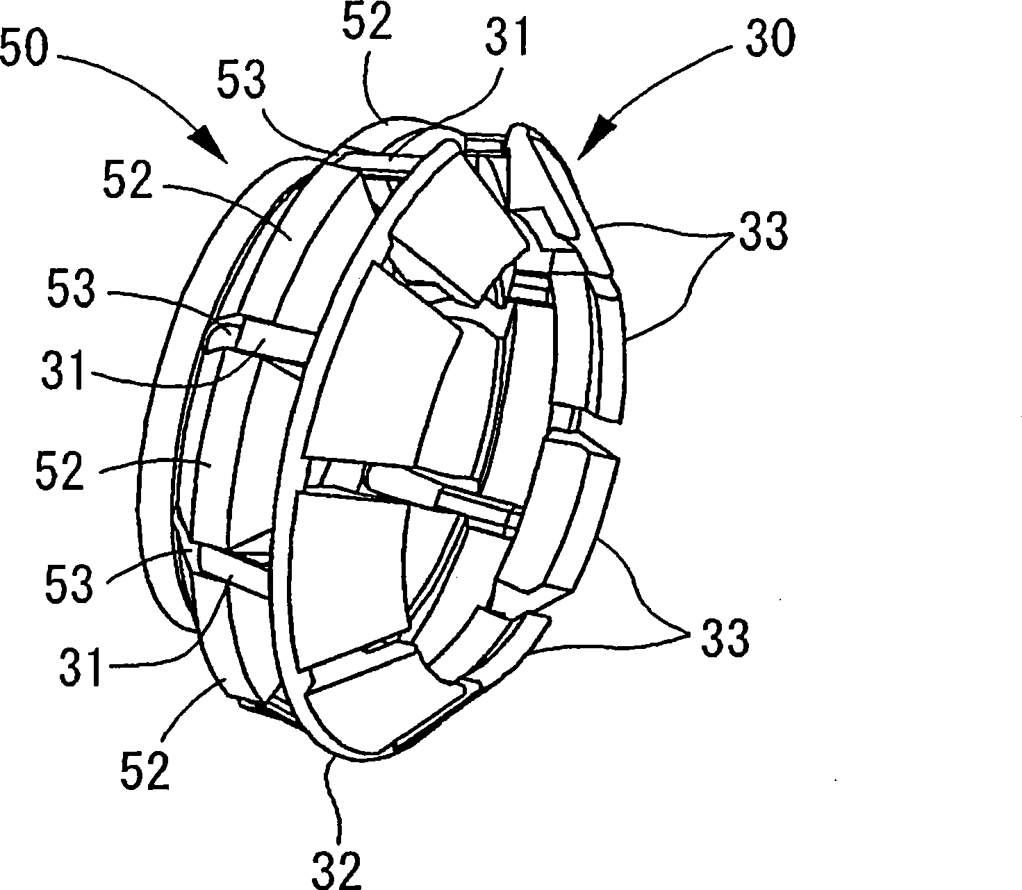
[0143] The first embodiment of the present invention uses Figure 1 to Figure 6 Be explained. figure 1 A half sectional view showing an embodiment of the corrugated pipe joint of the present invention, figure 2 Parts development perspective view showing an embodiment of the corrugated pipe joint of the present invention, image 3 A perspective view showing a state in which a retainer and a restraint member are fitted according to the present invention, Figure 4 A perspective view showing an embodiment of the elastic member of the present invention, Figure 5 A half-sectional view showing a state in which the bellows of the present invention is inserted into a joint for bellows, Image 6 A half sectional view showing a completed state of construction for connecting a bellows to the joint for bellows of the present invention.

[0144] like figure 1 and 2 As shown, the joint 1 for bellows has: a joint main body 10 having a through hole 16 into which the bellows T is inser...

no. 2 approach 〕

[0174] Next, use Figure 7 ~ Figure 11 A second embodiment will be described. Figure 7 A half sectional view showing a second embodiment of the corrugated pipe joint of the present invention, Figure 8 A perspective view showing an example of the constraining member of the second embodiment of the present invention, Figure 9 A half-sectional view showing a state where a bellows is inserted into a second embodiment of the joint for bellows of the present invention, Figure 10 A half-sectional view showing the construction completion state of the second embodiment of the bellows joint of the present invention for connecting the bellows, Figure 11 A half cross-sectional view showing a state in which the push nut is slid when the bellows is insufficiently inserted in the second embodiment of the joint for bellows of the present invention.

[0175] Additionally, with Figure 1 to Figure 6 The same structures of the shown bellows joints are denoted by the same reference numer...

no. 3 approach 〕

[0186] Next, refer to Figure 12 to Figure 15 A third embodiment will be described. Figure 12 It is a half-sectional view of a third embodiment of a joint for bellows of the present invention, Figure 13 A half-sectional view showing a state in which a bellows is inserted into a third embodiment of the joint for bellows of the present invention, Figure 14 A half sectional view showing the construction completion state of the connection bellows of the third embodiment of the joint for bellows of the present invention, Figure 15 A half cross-sectional view showing a state in which the push nut is slid when the bellows is insufficiently inserted in the third embodiment of the joint for bellows of the present invention.

[0187] Additionally, with Figure 1 to Figure 6 The same structures of the shown bellows joints are denoted by the same reference numerals, and description thereof will be omitted.

[0188] like Figure 12 As shown, the bellows joint 1B has: a joint main ...


PUM


Abstract

The invention relates to a joint for a corrugated pipe, which can reliably insert the corrugated pipe into a stated position. The joint (1) for the corrugated pipe comprises: a joint body (10) provided with a through hole (16) for inserting the corrugated pipe (T), a press nut (20) which can slide in the inside direction of the through hole (16) and one end of which is inserted with the through hole (16), an annular stoppage component (50) one end of which forms a plurality of partition parts (53), a restraining component (30) forming a projecting part (31) inserted on the partition parts (53), a sealing component (40) on the outer peripheral face of the sealed corrugated pipe (T), an elastic component (70) kept in a compressed state, and a movable component (80) pressed by the front end of the corrugated pipe (T) and sliding in the inside direction of the through hole (16). When the movable component (80) pressed by the corrugated pipe (T) can slide in the inside direction of the through hole (16), the compressed state of the elastic component (70) is opened, so that the projecting part (31) inserted with the partition parts (53) is released.

Description

technical field [0001] The present invention relates to a bellows joint for connecting bellows used for gas supply piping and the like, and particularly relates to improvement of sealing performance and workability for long-term use. Background technique [0002] In general, in gas supply piping such as city gas, meandering flexible pipes made of metal bellows and joints for bellows connecting them are widely used from the viewpoint of workability and the like. As a joint for bellows, for example, Patent Document 1 describes a joint for bellows, which has: a main body having an inner hole inserted into the end of the bellows and a connecting portion connected to other pipes; The claw in the concave part locks the retainer of the bellows; the sealing mechanism that seals between the bellows and the main body; engages slidably with respect to the main body and locks the bellows on the main body at a specific sliding position The state locks the retainer cylinder of the retain...

Claims


Application Information

Patent Timeline
Patent Type & Authority Applications(China)
IPC IPC(8): F16L33/00F16L33/26
Inventor 石部文和猪谷崇明荒木悟
Owner HITACHI METALS LTD
Why Eureka
Try Eureka