
Constituted body for building and its mfg. method

一种建筑物、加强体的技术,应用在建筑物构造、建筑构件、建筑等方向,能够解决不能简单地修正隔板姿势、作业困难、作业性差等问题

Inactive Publication Date: 2004-05-26
平垣实
View PDF1 Cites 8 Cited by
  • Summary
  • Abstract
  • Description
  • Claims
  • Application Information

AI Technical Summary

Problems solved by technology

[0004] This technique is described in the same literature as figure 2 As shown, since the separator is inserted into the steel pipe from the small opening of the steel pipe, it is very difficult to hold the separator and insert it into the steel pipe correctly, and the workability is extremely poor.
[0005] In addition, once the partition plate is inserted into the steel pipe, if the posture of the partition plate is not in the correct state perpendicular to the longitudinal direction of the steel pipe, the posture of the partition plate cannot be easily corrected.

Method used


Image

  • Constituted body for building and its mfg. method
  • Constituted body for building and its mfg. method
  • Constituted body for building and its mfg. method

Examples


Embodiment Construction

[0075] Hereinafter, embodiments of the building structure of the present invention and its manufacturing method will be described based on the drawings.

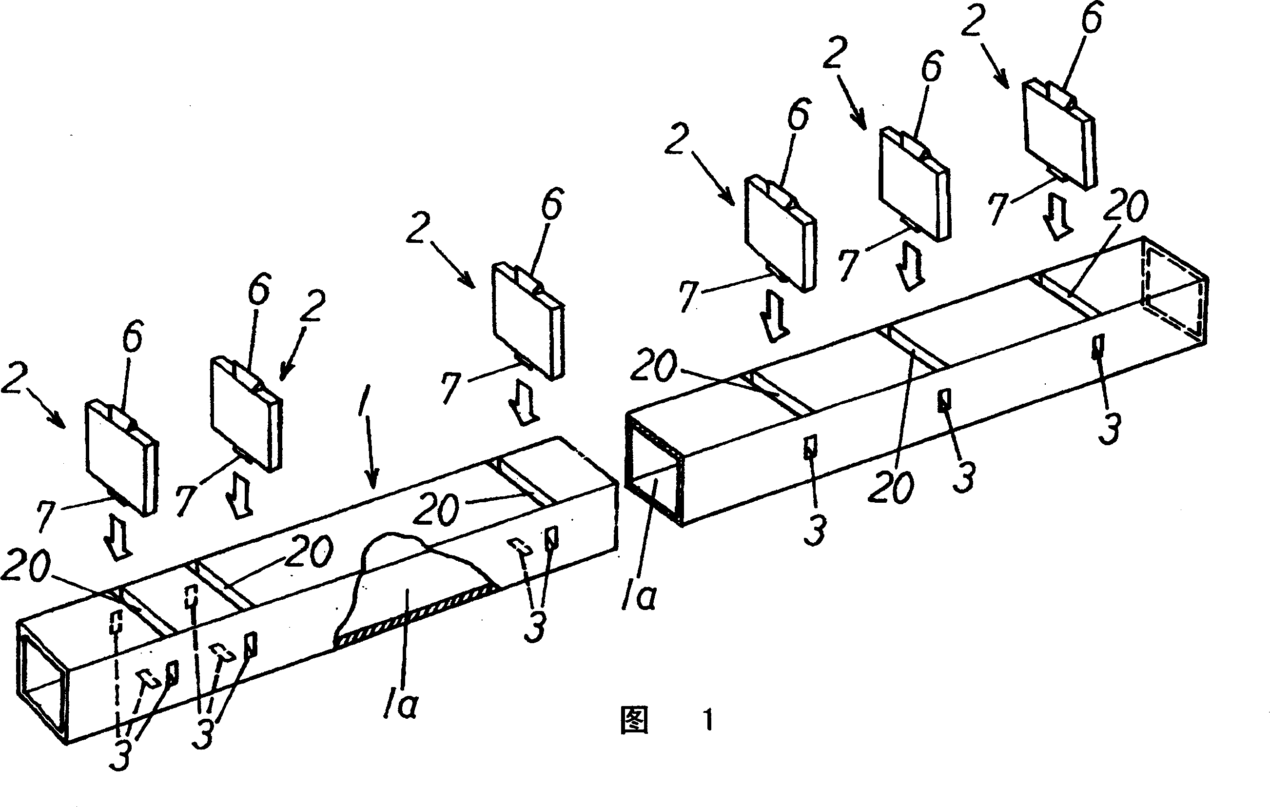
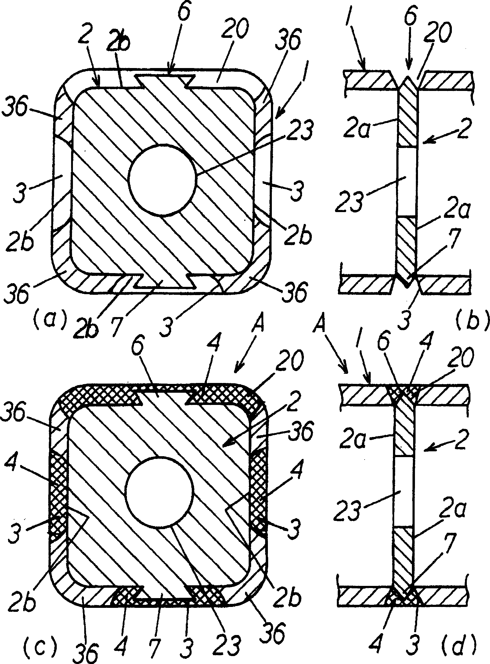
[0076] figure 2 with Figure 6 ~ Figure 10 , Picture 12 , Figure 14 Middle A is a structural body for buildings, which is used as a column body that becomes a vertical member for constructing steel frame structures and other structures, and a beam body that becomes a horizontal member or an inclined member. As shown in FIG. 1, it has a hollow interior. The continuous elongated steel pipe component 1 and the reinforcement 2 provided in the hollow portion 1a inside the steel pipe component 1 so as to cross the inside of the steel pipe component 1 in the longitudinal direction are provided on the outer peripheral portion of the steel pipe component 1 In the plurality of joint holes 3, the steel pipe member 1 and the reinforcement body 2 are fastened together by welding joint 4.

[0077] The aforementioned steel pipe member 1 is...


PUM


Abstract

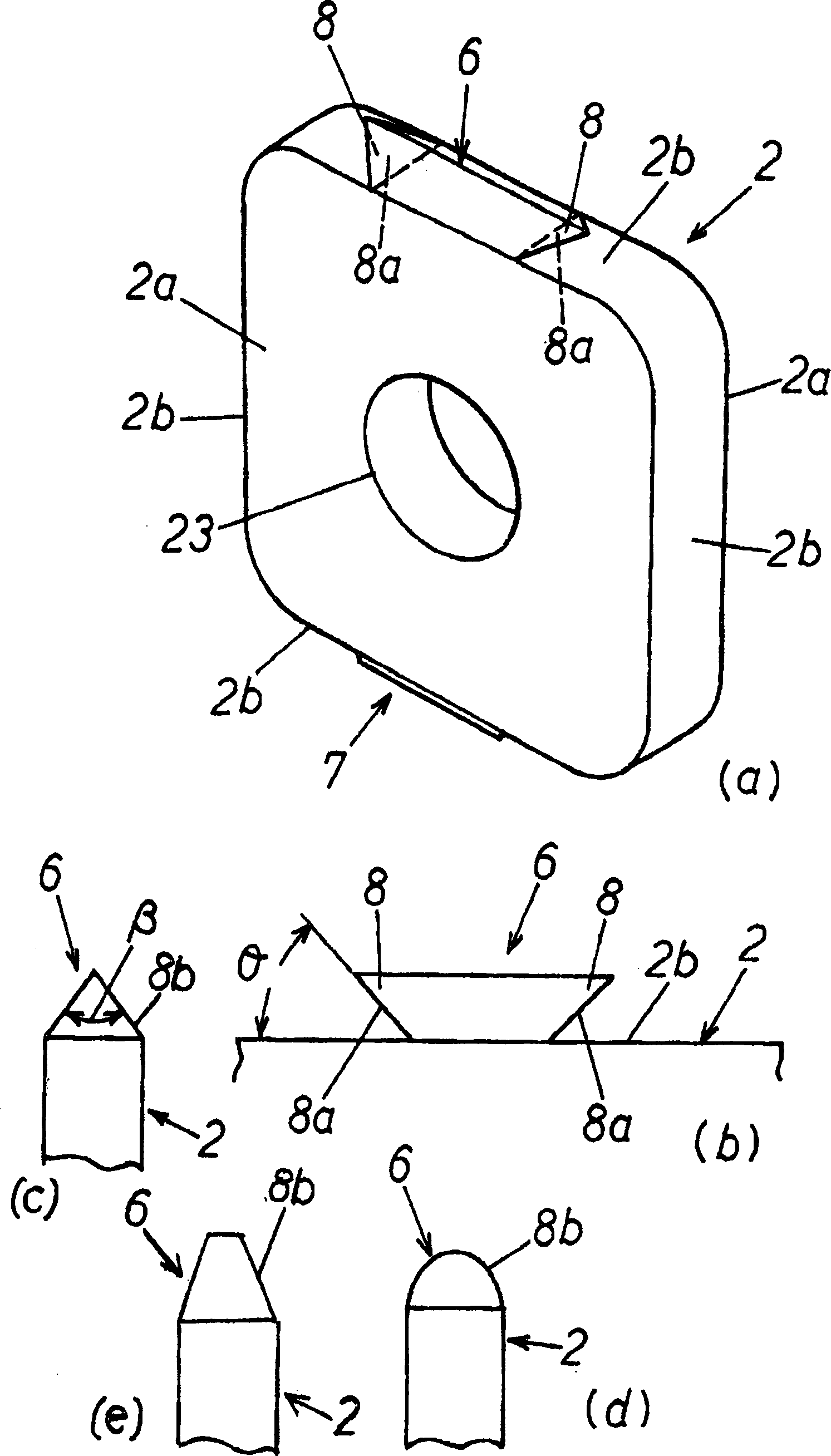
It is an object to provide a construct for buildings and a method for manufacturing the same exhibiting favorable workability through a simple structure and capable of achieving high strength and accuracy when used in structural steelworks constructed through constructs for buildings such as pillar elements or beam elements; for achieving this object, the construct A for buildings comprises a steel pipe member 1 and reinforcing elements 2 provided in a hollow portion 1a of the interior of the steel pipe member 1 to cross the interior of the steel pipe member 1 in the longitudinal direction, with the steel pipe member and the reinforcing elements being welded and joined; wherein inserting holes 20 for the reinforcing elements are formed at mounting positions for the reinforcing elements on an outer peripheral portion of the steel pipe member to have a width meeting width dimensions of the reinforcing elements, wherein these inserting holes are successively formed from the outer peripheral surface of the steel pipe member to the interior thereof, and wherein the reinforcing elements are inserted from these inserting holes from the outer peripheral surface of the steel pipe member to the interior in a direction that is substantially orthogonal to the longitudinal direction of the steel pipe member.

Description

Technical field [0001] The present invention relates to a steel frame structure constructed of a building structure such as a column or a beam, which has a simple structure, good workability, and can obtain a high strength and high precision building structure and a manufacturing method thereof . Background technique [0002] Conventionally, a steel pipe structure in which a partition is inserted into a steel pipe in a steel frame building and the steel pipe is reinforced by the partition is known (for example, refer to Patent Document 1). [0003] Patent Document 1: JP 2002-146921 A. [0004] This technique is in the same literature as figure 2 As shown, because the partition is inserted into the steel pipe from the small opening of the steel pipe, the work of holding the partition and inserting it into the steel pipe is very difficult, and the workability is extremely poor. [0005] In addition, once the partition is inserted into the steel pipe, when the posture of the partit...

Claims


Application Information

Patent Timeline
Patent Type & Authority Applications(China)
IPC IPC(8): E04B1/24B23K9/00B23K9/028E04C3/04E04C3/29E04C3/32E04C3/34E04C3/36
CPCE04C2003/0447E04C2003/043B23K2201/04E04C2003/0465E04C3/29E04C3/32E04C3/34E04C3/04E04C3/36B23K2101/04E04B1/24
Inventor 平垣实
Owner 平垣实
Learn More