Device for positioning multiple function elements

A technology of functional elements and heating devices, which is applied in the field of devices for positioning multiple functional elements, and can solve problems such as complex guidance

Active Publication Date: 2014-07-23
MAHLE INT GMBH
View PDF10 Cites 6 Cited by
  • Summary
  • Abstract
  • Description
  • Claims
  • Application Information

AI Technical Summary

Problems solved by technology

However, the disadvantage of using the device according to the invention is that th

Method used


Image

  • Device for positioning multiple function elements
  • Device for positioning multiple function elements
  • Device for positioning multiple function elements

Examples


Embodiment Construction

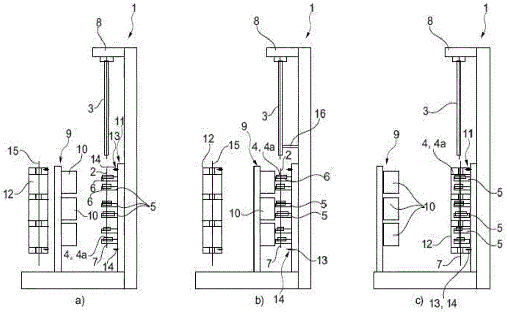
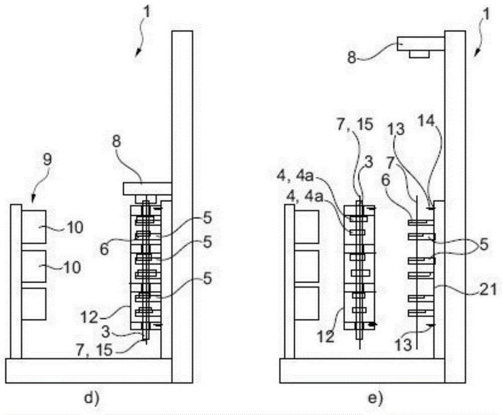
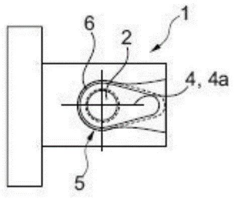
[0025] according to figure 1 a~e, image 3 with Figure 7 , the device 1 for positioning a plurality of functional elements 4 according to the invention comprises a plurality of bases 5 intended for each functional element 4, the device 1 comprising a shaft 3 positioned at a predetermined angular position on the shaft 3 The concave part 2. In each base 5 formed in the shape of a table, a respective molded recess 6 is provided, via which the corresponding received functional element 4, 4a on the shaft 3 can be fixed in an angular position corresponding to the angular position of the corresponding functional element 4, 4a. The functional element 4, such as the cam 4a. With the die groove 6 , an exact angular alignment of the functional element 4 and the cam 4 a relative to the shaft 3 takes place, which in the case of a camshaft is of decisive importance for controlling the valves of an internal combustion engine. The base 5 and thus also the formwork 6 are arranged vertical...


PUM


Abstract

The invention relates to an apparatus (1) for assembling a composite arrangement, consisting of a plurality of functional elements (4) on a shaft (3), said elements having an aperture (2) for the shaft (3), wherein the apparatus (1) has a plurality of retaining devices (5) each intended for accommodating a functional element (4). It is pertinent to the invention here that the retaining devices (5) are arranged vertically one above the other, that a vertically displaceable guide carriage (8) is provided for the shaft (3), in which case the shaft (3) is joined to the functional elements (4) in the vertical direction, that there is a separately arranged heating device (9) provided, it being possible for at least two functional elements (4) to be heated simultaneously thereby, and that a gripping device (10) is provided, it being possible for the latter to remove preferably all the functional elements (4) together from the heating device (9) and introduce them into the retaining devices (5) of the apparatus (1). This makes it possible to dispense with high-outlay guidance of the shaft (3), which has been necessary hitherto, during the joining operation.

Description

technical field [0001] The invention relates to a device for positioning functional elements according to the preamble of claim 1 , including recesses for shafts, in particular cams; balancing masses; gears and / or bearings. The invention furthermore relates to a method for thermally joining a shaft and a plurality of functional elements. Background technique [0002] DE 10 2008 064 194 A1 discloses a general device for positioning a plurality of functional elements, comprising a recess for a shaft, in particular a cam, which is located at a predetermined angular position on the shaft, wherein the device comprises a respective function element a plurality of bases, which in each case are fitted with molded cavities which fix the angular position of the respective functional element corresponding to the angular position on the shaft. The individual bases in this case can be positioned in such a way that the recesses of the functional elements lie on a common straight line. A...

Claims


Application Information

Patent Timeline
IPC IPC(8): B23P19/04B23P19/10B23P13/00B23P11/02
CPCB23P11/025B23P2700/02F01L1/047F01L2001/0471F16B4/006F01L2303/01F16D1/0858F16H53/025Y10T29/49293Y10T29/49826Y10T29/49865Y10T29/49867Y10T29/53439Y10T74/18296F16H25/16
Inventor 克里斯托弗·贝伦斯安东尼奥·梅农纳洛塔尔·普菲策恩迈尔罗兰·沙赫雷尔
Owner MAHLE INT GMBH
Why Eureka
Try Eureka