Defrosting method for low temperature dehumidifier

A dehumidifier, low-temperature type technology, applied in refrigerators, damage protection, refrigeration components, etc., can solve the problems of reduced heat transfer efficiency of evaporators, reduced heat transfer effects of evaporators, and easy damage of solenoid valves, etc., to achieve simple structure, Good defrosting effect and low cost

Inactive Publication Date: 2009-03-11
LG ELECTRONICS (TIANJIN) APPLIANCES CO LTD
View PDF1 Cites 15 Cited by
  • Summary
  • Abstract
  • Description
  • Claims
  • Application Information

AI Technical Summary

Problems solved by technology

That is, through the electromagnetic valve, a part of the high-temperature and high-pressure refrigerant is directly introduced into the evaporator for a period of time to defrost. The disadvantage is that the heat exchange effect of the evaporator is reduced.
[0013] 4. Reversing defrosting, as shown by the dotted line in Figure 2, that is, using the reversing valve 10 to change the refrigerant circulation direction in the dehumidifier, and directly transport the high-temperature and high-pressure refrigerant compressed by the compressor 1 to the evaporator 3 for a period of time for defrosting. Frost, after the evaporator is defrosted, the refrigerant returns to the compressor 1 through the expansion valve 9 and the condenser 2. The disadvantage is that the heat exchange efficiency of the evaporator is reduced, and the solenoid valve is easily damaged.

Method used


Image

  • Defrosting method for low temperature dehumidifier
  • Defrosting method for low temperature dehumidifier
  • Defrosting method for low temperature dehumidifier

Examples


Embodiment Construction

[0029] In order to further illustrate content of the present invention, technical scheme, give following example again and illustrate as follows in conjunction with accompanying drawing:

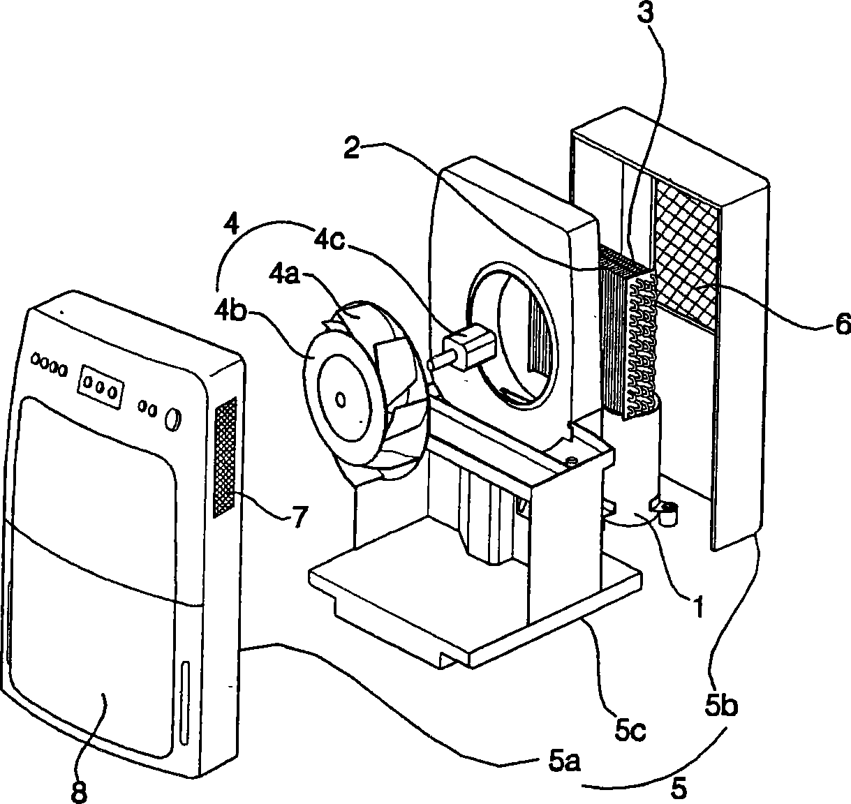
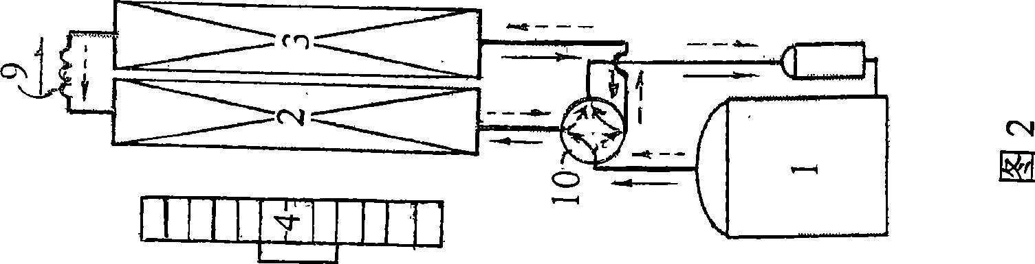
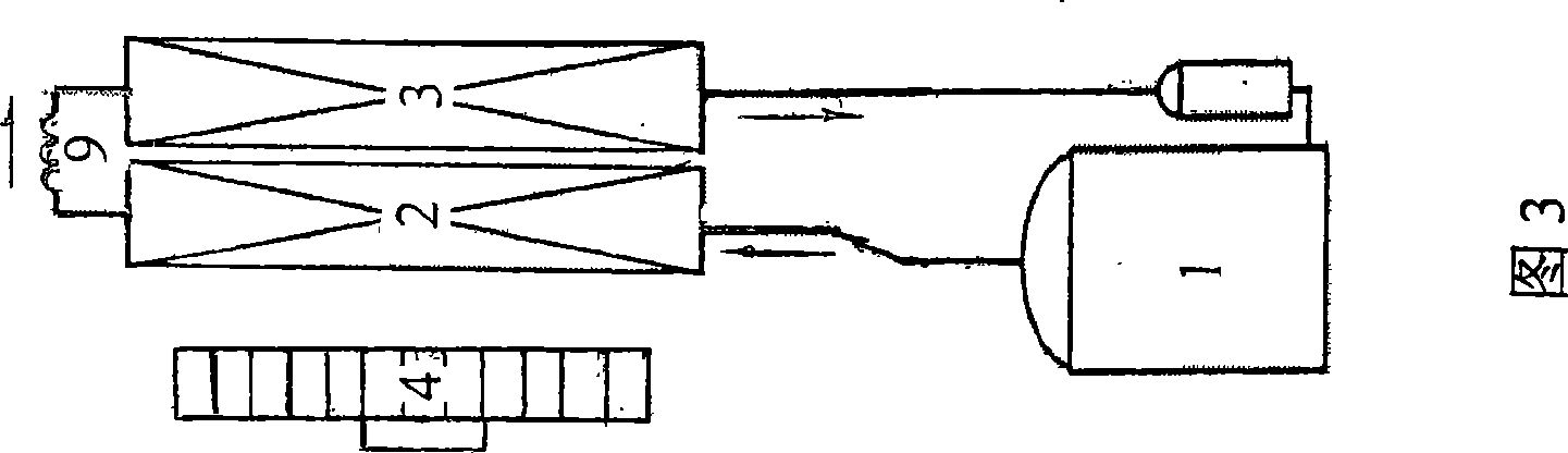
[0030] As shown in Figures 3, 5, and 7, the defrosting method of the low-temperature dehumidifier of the present invention is to use the dehumidifier evaporator to send the temperature sensing head temperature signal to the dehumidifier in the refrigerant circulation pipeline of the dehumidifier shown in Figure 3 The middle controller (not shown) is controlled by the controller to open and close the operation of the compressor and adjust the air volume of the fan. It is a low-temperature dehumidifier defrosting method that relies on air flow to defrost the evaporator, such as Figure 5 , 7 In the example shown, it runs for 20 minutes with the compressor turned on and the fan at the set air volume for dehumidification. At the same time, the temperature of the exhaust pipe of the evaporator is...


PUM


Abstract

The invention relates to a defrosting technology of a dehumidifier, in particular to a defrosting method of a low-temperature dehumidifier which stops a compressor and increases the wind volume of a fan. The defrosting method can solve the problems that a direction changing valve is currently used for changing the direction of a circulating refrigerant for defrosting, while the direction changing valve is expensive and easily damaged. The technical proposal is as follows: the compressor is started and the fan is operated under the set wind volume, then the dehumidification is operated for a period of time and the temperature of an exhaust pipe of the evaporator is simultaneously judged, if the temperature thereof is higher than the defrosting inrush temperature, the dehumidification is continuously carried out, and if the temperature is not higher than the defrosting inrush temperature, the compressor is closed, the wind volume of the fan is increased, and the defrosting is started; the temperature of the exhaust pipe of the evaporator is simultaneously judged, when the temperature is higher than the defrosting release temperature, the dehumidification state is returned, if the temperature is still not higher than the defrosting release temperature, the defrosting is continuously carried out till the temperature is higher than the defrosting release temperature under the situations that the compressor is closed and the wind volume of the fan is increased, and then the dehumidification state is returned. The defrosting method reduces the cost of the dehumidifier and save the electricity charge due to the elimination of the direction changing valve.

Description

technical field [0001] The invention relates to the defrosting technology of a dehumidifier, in particular to a defrosting method for a low-humidity dehumidifier which stops a compressor and accelerates the operation of a motor. Background technique [0002] Generally speaking, after the dehumidifier introduces the humid air in the room into the inside of the cabinet, it passes through the heat exchanger formed by the evaporator and the condenser that flows the refrigerant inside to reduce the humidity, and then discharges the air with reduced humidity back to the cabinet. to indoors. [0003] figure 1 It is an exploded perspective view of a general conventional dehumidifier. [0004] Such as figure 1 As shown, the structure of the dehumidifier in the prior art includes: a compressor 1 installed on the chassis to compress the refrigerant; a condenser 2 connected to the outlet of the compressor to exchange heat between the refrigerant compressed by the compressor and the s...

Claims


Application Information

Patent Timeline
Patent Type & Authority Applications(China)
IPC IPC(8): F25B47/02
Inventor 杨成立
Owner LG ELECTRONICS (TIANJIN) APPLIANCES CO LTD
Why Eureka
Try Eureka