
Determining device and method for step motor stop state

A stepping motor and judging device technology, applied in the direction of motor generator control, electrical components, information recording on disk, etc., can solve the problems of occupying space and increasing the cost of mechanism design micro-switches, etc.

Inactive Publication Date: 2009-03-11
AMTEK SEMICON
View PDF0 Cites 13 Cited by
  • Summary
  • Abstract
  • Description
  • Claims
  • Application Information

AI Technical Summary

Problems solved by technology

This will undoubtedly occupy the space of the entire stepper motor control system, and correspondingly increase the cost of the mechanism design and the micro switch

Method used


Image

  • Determining device and method for step motor stop state
  • Determining device and method for step motor stop state
  • Determining device and method for step motor stop state

Examples


Embodiment Construction

[0051] The implementation of the present invention is described below through specific specific examples, and those skilled in the art can easily understand other advantages and effects of the present invention from the content disclosed in this specification. The present invention can also be implemented or applied through other different specific embodiments, and various modifications and changes can be made to the details in this specification based on different viewpoints and applications without departing from the spirit of the present invention.

[0052] The following examples further illustrate the viewpoints of the present invention in detail, but do not limit the scope of the present invention in any respect.

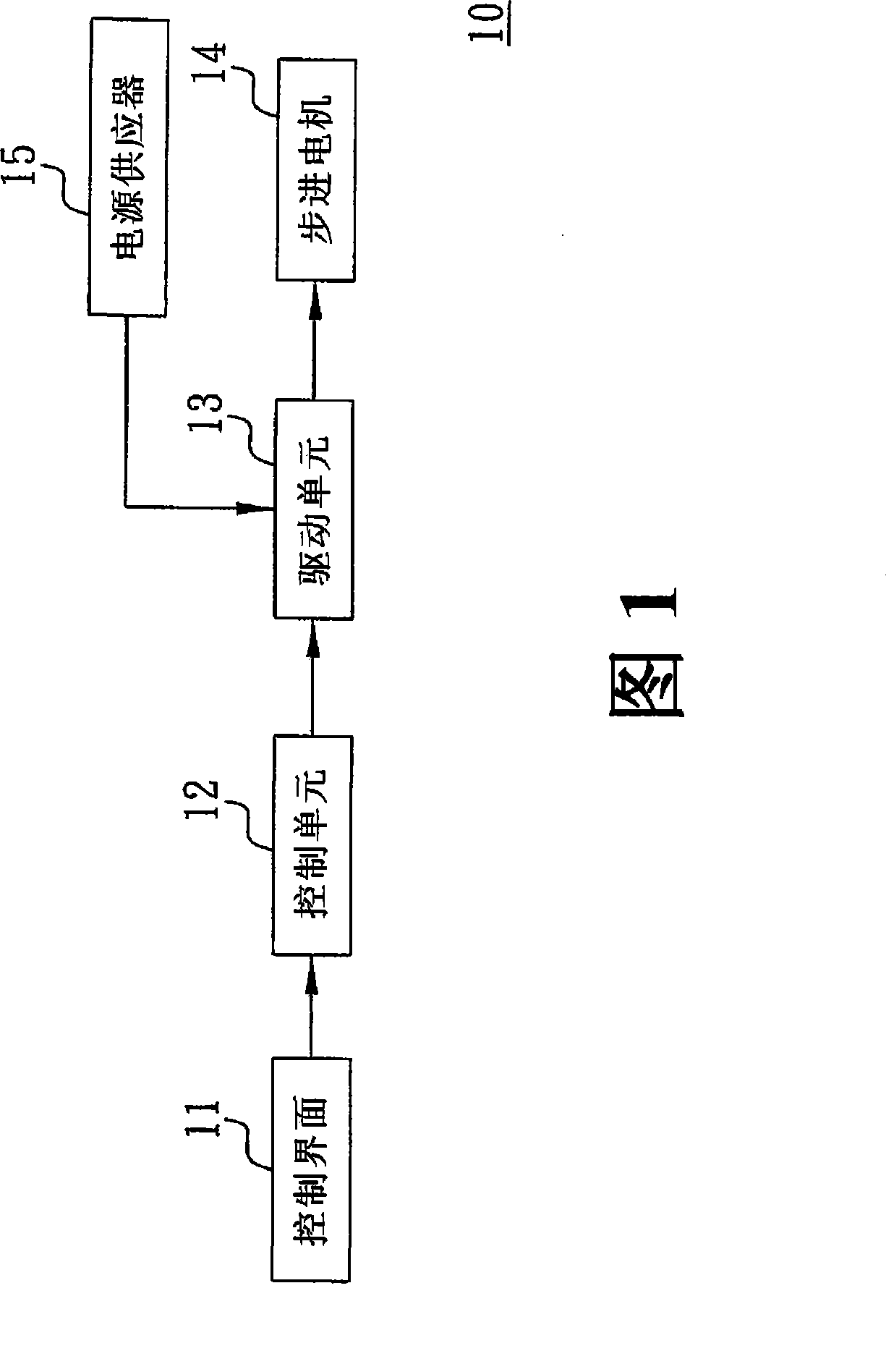
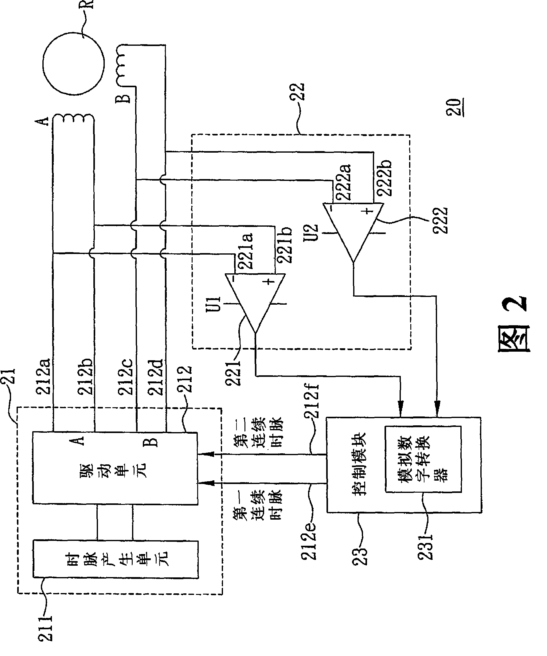
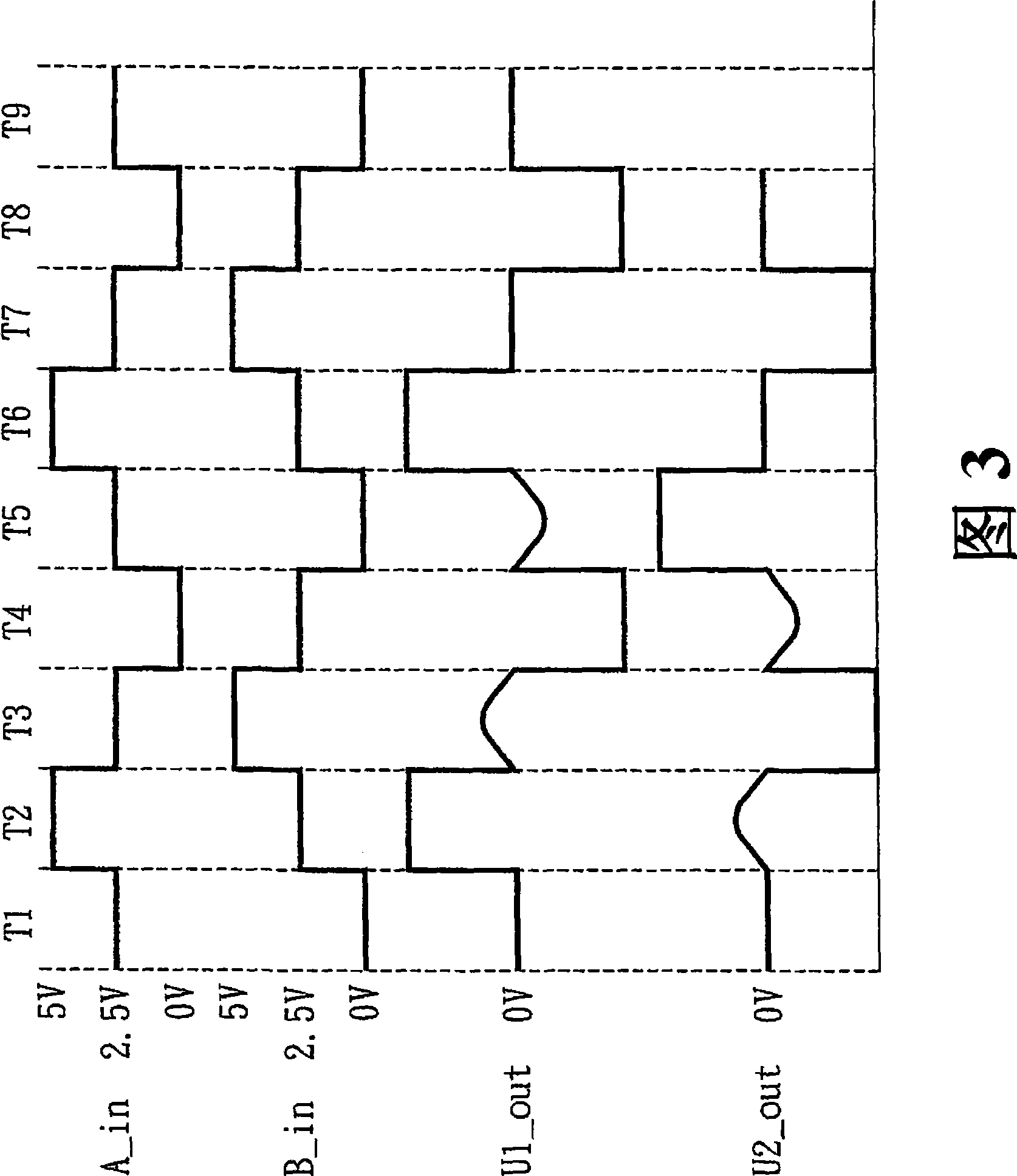
[0053] Referring to FIG. 2 , it is a schematic block diagram illustrating the basic structure of the device for judging the stalled state of the stepping motor of the present invention. As shown in the figure, the judging device 20 at least includes: a driving ...


PUM


Abstract

The invention discloses a judging device and a judging method for judging the stopping and rotating states of a step motor. The device is applied to the step motor with at least two stator windings and a rotor, and is characterized in that the continuous clock pulses of at least two different phases are respectively produced through a driving module, and are sent to the two stator windings, so as to enable the rotor to run and let the stator windings to produce back electromotive force with intervals in turn, then a control module, the threshold voltage of which is preset, is used for alternately inputting a sensing time interval to the driving module in a way of corresponding to the continuous clock pulses of at least two different phases, so as to enable a sensing module to sense out the back electromotive force produced by the stator windings according to the sensing time interval, and carry out the comparison between the back electromotive force and the threshold voltage, thereby letting the control module to judge the stopping and rotating states of the step motor when the back electromotive force is lower than the threshold voltage, and correspondingly outputting a stopping and rotating state signal, so that not only the problems that a micro switch is usually required to be added and the space of the original step motor control system is occupied are solved, but also the cost in structural design and added elements is saved.

Description

technical field [0001] The present invention relates to a judging device and judging method for a stalled state of a stepping motor, more specifically, relates to a judging device and a judging method applied to a stepping motor with at least two stator windings and a rotor. Background technique [0002] Because of its very simple control method, stepping motors have been widely used in various control systems to control the speed, displacement and direction of load devices. The difference between the stepper motor and the general motor is that when the stepper motor receives power, the rotor (rotor) will not rotate periodically, that is, the stepper motor is a mechanical device that accepts digital signal control. , and the magnetic field of the pole (pole) on the stator (stator) is continuously switched alternately to drive the rotor to rotate, and whenever a digital clock signal pulse is input, the rotor of the stepper motor will rotate by a fixed angle, which is also Th...

Claims


Application Information

Patent Timeline
IPC IPC(8): H02P8/34G11B19/14
Inventor 张得宜曾祥伟
Owner AMTEK SEMICON
Learn More