
Heat-resistant cast steel exhaust manifold

A technology of exhaust manifold and heat-resistant cast steel, which is applied in the direction of exhaust devices, casting molds, gas chambers, etc., can solve the problems of increased man-hours and lower ratios, and achieve less man-hours yield, light weight and heat-resistant deformation sexual effect

Inactive Publication Date: 2009-03-11
HITACHI METALS LTD
View PDF1 Cites 0 Cited by
  • Summary
  • Abstract
  • Description
  • Claims
  • Application Information

AI Technical Summary

Problems solved by technology

However, since the riser does not become a product, there is a problem that the ratio of the product to the injected melt decreases
In addition, the riser must be removed after manufacture, which increases man-hours

Method used


Image

  • Heat-resistant cast steel exhaust manifold
  • Heat-resistant cast steel exhaust manifold
  • Heat-resistant cast steel exhaust manifold

Examples


Embodiment 1~14

[0024] Examples 1-14, Comparative Examples 1-3

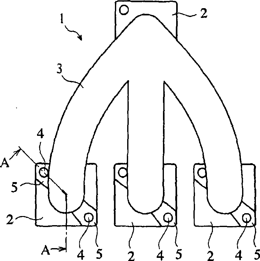
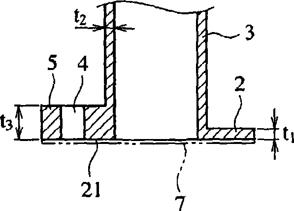
[0025] The exhaust manifold shown in FIG. 1 was cast from an austenitic cast steel having a composition of C: 0.45%, Si: 1.2%, Mn: 1.0%, P: 0.015%, S: 0.015%, Ni: 10%, Cr: 20%, Nb: 1.5%, and W: 3.0% (Examples 1-8, Comparative Examples 1-3). Thickness t of flange part 2 1 , the thickness t of the port part 3 2 , and the thickness t of the peripheral portion 5 of the bolt hole 4 3 Indicated in Table 1. Also, using the same austenitic heat-resistant cast steel, the exhaust manifolds (Examples 9 to 14) shown in FIG. 4( a ) were cast. except t 1 ~t 3 In addition, the thickness t of the protruding part 11 4 Indicated in Figure 1.

[0026] The yield (man-hour) of each exhaust manifold and the thermal deformation of the flange portion due to the use of the exhaust manifold were evaluated as follows. The results are shown in Table 1.

[0027] (1) Evaluation of yield (man-hours)

[0028] ◯: Even if no riser is provided in the f...


PUM


Abstract

Provided is a heat-resistant cast steel exhaust manifold includes: a plurality of flange portions having a hole for connection by a bolt to an exhaust port of an engine cylinder head; a plurality of port portions connected to the flange portions; and a confluence portion where the port portions are collected. The flange portion has a thickness equal to 80 to 150% of the thickness of the port portion.

Description

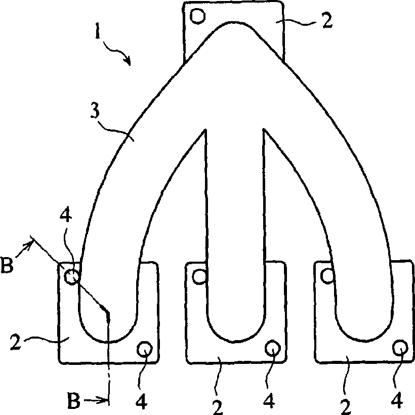
technical field [0001] The present invention relates to an exhaust manifold made of heat-resistant cast steel, which can be manufactured with a small man-hour and has high yield, and is lightweight and excellent in heat deformation resistance. Background technique [0002] The exhaust manifold that collects the exhaust gas from the engine and is connected to the exhaust pipe includes: a plurality of flange parts having holes connected to the exhaust port of the cylinder head on the upper part of the engine with bolts, a port part on each flange part, A converging part where a plurality of port parts join. In a general exhaust manifold, as described in JP-A-10-26018, the flange portion is thicker than the port portion in order to prevent thermal deformation of the flange portion due to high-temperature exhaust gas ( FIG. 2 ). For example, the average thickness of the flange portion is about 12 mm, and the average thickness of the port portion is about 5 mm. When manufacturi...

Claims


Application Information

Patent Timeline
Patent Type & Authority Applications(China)
IPC IPC(8): F01N7/10B22C9/24F01N13/10F01N13/08
CPCF01N2450/22F01N13/10B22C9/24F01N13/1861F01N2530/00F01N13/1805F01N13/08
Inventor 木村浩文早田智臣铃木雅直
Owner HITACHI METALS LTD
Learn More