
Imaging lens and imaging apparatus

一种摄像透镜、透镜的技术,应用在图像通信、运输和包装、电视等方向,达到提高安全性、降低错误认知、良好光学性能的效果

Inactive Publication Date: 2009-03-18
FUJI PHOTO OPTICAL CO LTD
View PDF0 Cites 29 Cited by
  • Summary
  • Abstract
  • Description
  • Claims
  • Application Information

AI Technical Summary

Problems solved by technology

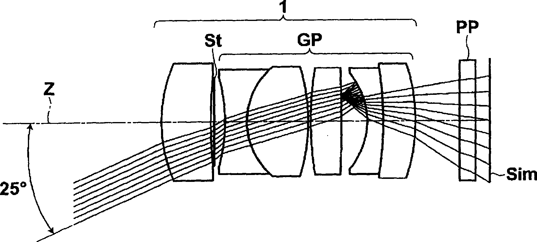
[0005] However, after the oncoming car passes by and the image of the headlight disappears from the screen, multiple reflections of the light passing through the headlight outside the screen will also appear in the screen.

Method used


Image

  • Imaging lens and imaging apparatus
  • Imaging lens and imaging apparatus
  • Imaging lens and imaging apparatus

Examples


Embodiment 1

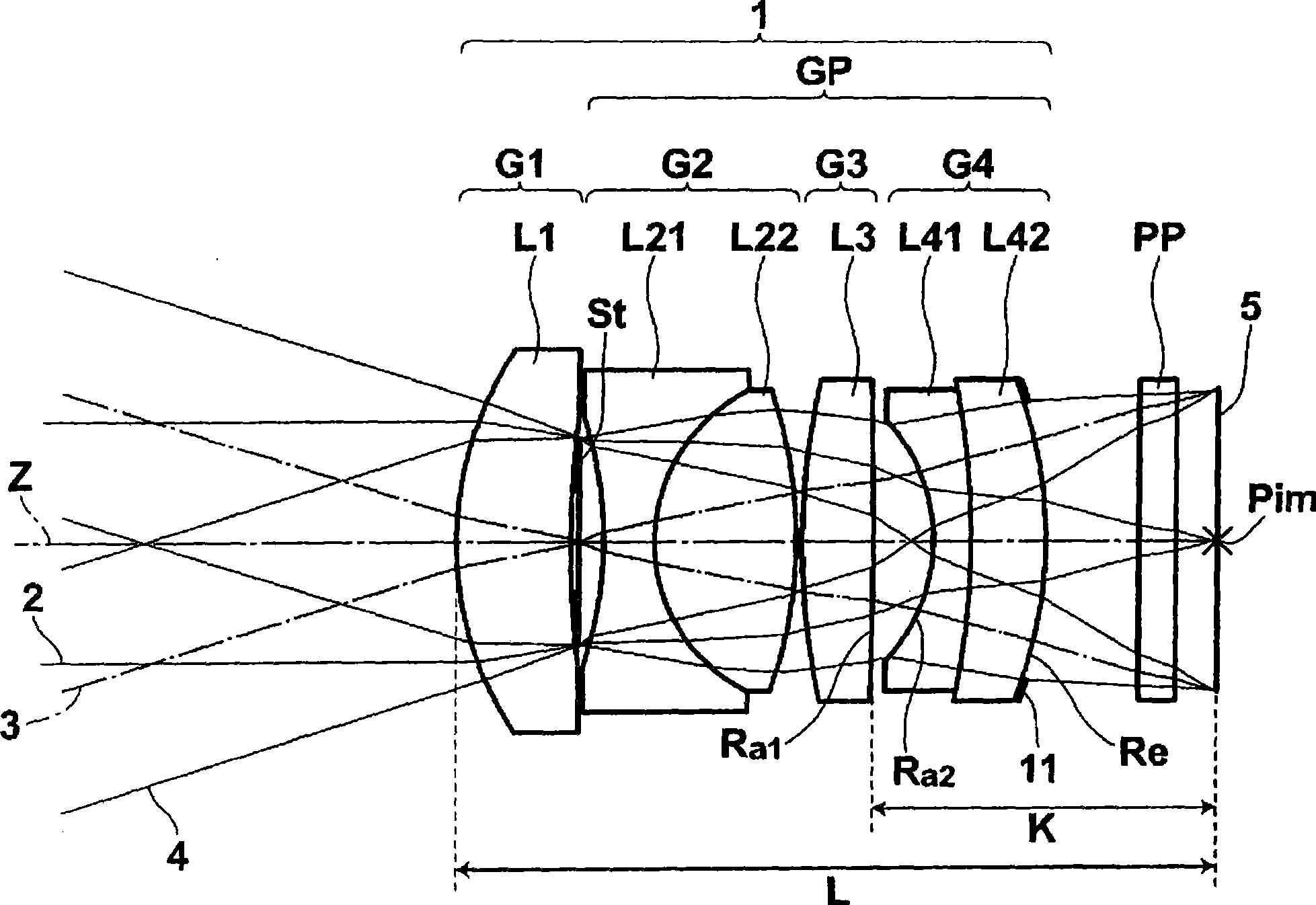
[0106] Table 1 shows the lens data and various data of the imaging lens according to Example 1. In the lens data in Table 1, the surface number indicates the i-th (i=1, 2, 3, ...) surface that increases sequentially toward the image side, taking the surface of the component closest to the object side as the first surface No. In addition, the lens data of Table 1 also includes the addition of the aperture stop St and the optical part PP.

[0107] Ri in Table 1 represents the radius of curvature of the i-th (i=1, 2, 3, ...) surface, and Di represents the light of the i-th (i=1, 2, 3, ...) surface and the i+1 surface Face spacing on axis Z. In addition, Ndj represents the refractive index with respect to the d-line of the j-th (i=1, 2, 3, . Indicates the Abbe number of the j-th optical element with respect to the d-line. In Table 1, the unit of the radius of curvature and surface interval is mm, and the radius of curvature is positive when the object is convex sideways, and n...

Embodiment 2

[0115] The lens data and various data of the imaging lens related to Example 2 are shown in Table 2, and the lens configuration diagram is shown in Figure 7 . exist Figure 7 , symbols Ri and Di correspond to Ri and Di in Table 2. In addition, Table 2 and Figure 7 The configuration example of the second embodiment shown does not include the optical component PP, but the lens system of the second embodiment may be used by inserting an optical component between the lens system and the imaging surface as in other embodiments.

[0116] [Table 2]

[0117] Example 2

[0118] face number Ri Di Ndj vdj 1 10.01 3.00 1.8348 42.7 2 52.27 0.21 3 (aperture aperture) ∞ 0.54 4 -8.10 0.85 1.7174 29.5 5 4.67 4.06 1.8348 42.7 6 -9.65 0.15 7 14.50 1.71 1.8348 42.7 8 106.69 1.60 9 -4.91 0.65 1.6129 37.0 10 -78.58 2.15 1.62041 60.3 11 -13.65 3.88 12 (image surface) ∞ ...

Embodiment 3

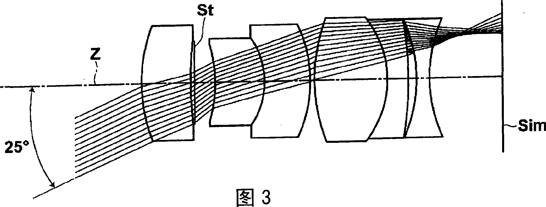
[0121] The lens data and various data of the imaging lens related to Example 3 are shown in Table 3, and the lens configuration diagram is shown in Figure 8 . exist Figure 8 Among them, symbols Ri and Di correspond to Ri and Di in Table 3.

[0122] [table 3]

[0123] Example 3

[0124] face number Ri Di Ndj vdj 1 6.20 2.54 1.7130 53.9 2 20.00 0.30 3 (aperture aperture) ∞ 0.50 4 -12.19 0.88 1.7174 29.5

[0125] FNo.=2.0, f=12.3, K=7.10, L=16.2, ω=17.0, Bf=3.76


PUM


Abstract

The invention provides an imaging lens and an imaging apparatus. The imaging lens (1) includes: a stop; and a lens group (GP) disposed between the stop and an imaging plane of the imaging lens and having a positive power as a whole. The lens group (GP) has an air lens formed by an air gap between lenses adjacent to each other, and the imaging lens satisfies conditional expression (1): -8 < L ( 1 / Ra 2 - 1 / Ra 1 ) < -3, Ra 1 represents a radius of curvature of an object-side surface of the air lens which has a convex shape and is closest to an image side of the imaging lens in the lens group, Ra 2 represents a radius of curvature of an image-side surface of the air lens, and L represents a distance on an optical axis of the imaging lens from an object-side surface of a lens closest to an object side in the imaging lens to an imaging plane.

Description

technical field [0001] The present invention relates to an imaging lens and an imaging device, and more particularly relates to an imaging lens and an imaging lens suitable for use in a vehicle-mounted camera and a monitoring camera using an imaging element such as a CCD (Charge Coupled Device) or a CMOS (Complementary Metal Oxide Semiconductor). An imaging device including the imaging lens. Background technique [0002] In recent years, imaging devices such as cameras have been installed in automobiles to take pictures of the front, side, and rear of the automobile to recognize the external environment, such as white line recognition on roads or obstacle detection, and other systems have been put into practical use. It is important that an on-vehicle lens suitable for such an on-vehicle camera has a bright optical system and good imaging performance. In addition, as a vehicle-mounted lens, it is also important to have a small exposed lens portion in terms of the appearance...

Claims


Application Information

Patent Timeline
Patent Type & Authority Applications(China)
IPC IPC(8): G02B13/00G02B1/11H04N5/225B60R11/04
CPCG02B13/146
Inventor 铃木隆浅见太郎
Owner FUJI PHOTO OPTICAL CO LTD
Learn More