
Slave node data interconnecting device, method and system base on one point to several points network

A node data, point-to-multiple technology, applied in the direction of selection devices, selection devices, electrical components, etc.

Active Publication Date: 2009-03-18
HONOR DEVICE CO LTD
View PDF0 Cites 26 Cited by
  • Summary
  • Abstract
  • Description
  • Claims
  • Application Information

AI Technical Summary

Problems solved by technology

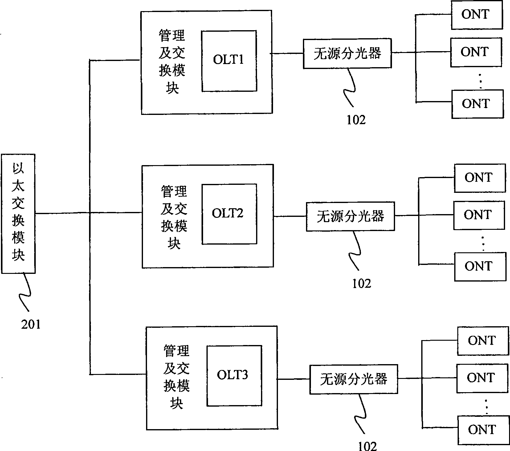
[0005] In the process of realizing the present invention, the inventor has found that there are at least the following problems in the prior art: under the networking architecture of the prior art 2, the Ethernet service flow between different slave nodes (such as ONT in PON) under the same P2MP system To intercommunicate, if these Ethernet traffic flows to the master node are not marked with a virtual local area network tag (Virtual Local Area Network Tag VLAN Tag) or are in the same virtual local area network (Virtual Local Area Network VLAN), they will be aggregated and interconnected in the Ethernet switch module are discarded, making it impossible to communicate with
The problem with this is that it puts constraints and restrictions on VLAN planning and application scenarios, and changes the freedom of using the original Ethernet.

Method used


Image

  • Slave node data interconnecting device, method and system base on one point to several points network
  • Slave node data interconnecting device, method and system base on one point to several points network
  • Slave node data interconnecting device, method and system base on one point to several points network

Examples


Embodiment 1

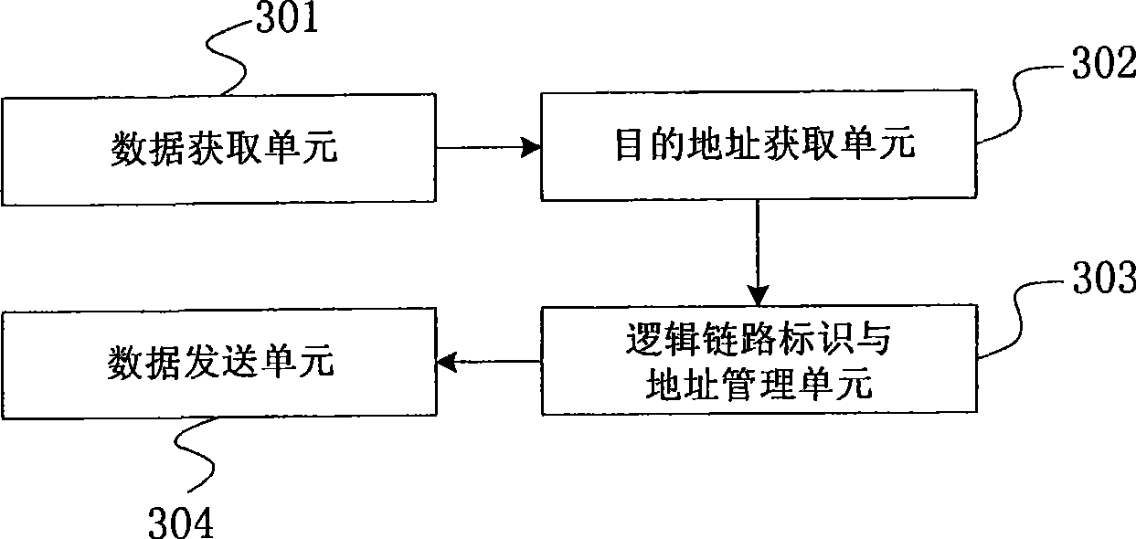
[0028] Such as image 3 Shown is a block diagram of the device structure of the embodiment of the present invention. The device is based on the point-to-multipoint network for data intercommunication between slave nodes, refer to image 3 , the device includes: a data acquisition unit 301 , a destination address acquisition unit 302 , a logical link identifier and address management unit 303 , and a data sending unit 304 . The data obtaining unit 301 is used to obtain the data sent by the communication initiation slave node; the destination address obtaining unit 302 is used to obtain the destination address of the data from the obtained data; the logical link identification and address management unit 303 is used to maintain the logical link According to the corresponding relationship between the identifier and the data address, according to the obtained destination address of the data, search for the logical link identifier corresponding to the destination address of the da...

Embodiment 2

[0031] On the basis of Embodiment 1, the data sending unit is further configured to: if the logical link identifier corresponding to the destination address of the data is not found from the correspondence between the logical link identifier and the data address, send the forward the acquired data to the uplink logical link of the master node; Broadcast data in all logical links other than the logical link of the above data.

[0032] The above-mentioned logical link identification and address management unit 303 specifically includes: a corresponding relationship learning module, which is used to establish the logical link according to the link identification and data address of the point-to-multipoint system of the data sent by each communication initiation slave node The corresponding relationship between the identifier and the data address; a storage module, configured to store the obtained data and the corresponding relationship between the logical link identifier and the ...

Embodiment 3

[0038] Such as Figure 4 Shown is a flow chart of the method of the embodiment of the present invention. The inventive method comprises the following steps:

[0039] Step 401: Obtain the data sent by the communication initiation slave node, the data includes the destination address of the data;

[0040] Step 402: Obtain the destination address of the data from the acquired data;

[0041] Step 403: According to the destination address of the obtained data, using its Ethernet destination MAC address as an index, search for the logical link identifier corresponding to the destination address of the data from the correspondence between the logical link identifier and the data address;

[0042] In the process of implementing step 403, if the logical link identifier corresponding to the destination address of the data is not found from the correspondence between the logical link identifier and the data address, the acquired data is forwarded to the master node's Uplink logical li...


PUM


Abstract

The embodiment provides a data inter-communication method, device and system for slave node based on one point-to-multiple points network. The method comprises obtaining data sent by the communication triggering slave node; obtaining destination address of the data from the obtained data; searching the logic link label corresponding to the destination address of the data in corresponding relation between the logic link label and the data address according to the obtained destination address of the data; sending obtained data to a destination logic link according to data destination address obtained by the search and corresponding logic link label. The invention overcomes the impact of the data intercommunication between nodes to the system in prior art, makes application scene return to flexibility of the Ethernet.

Description

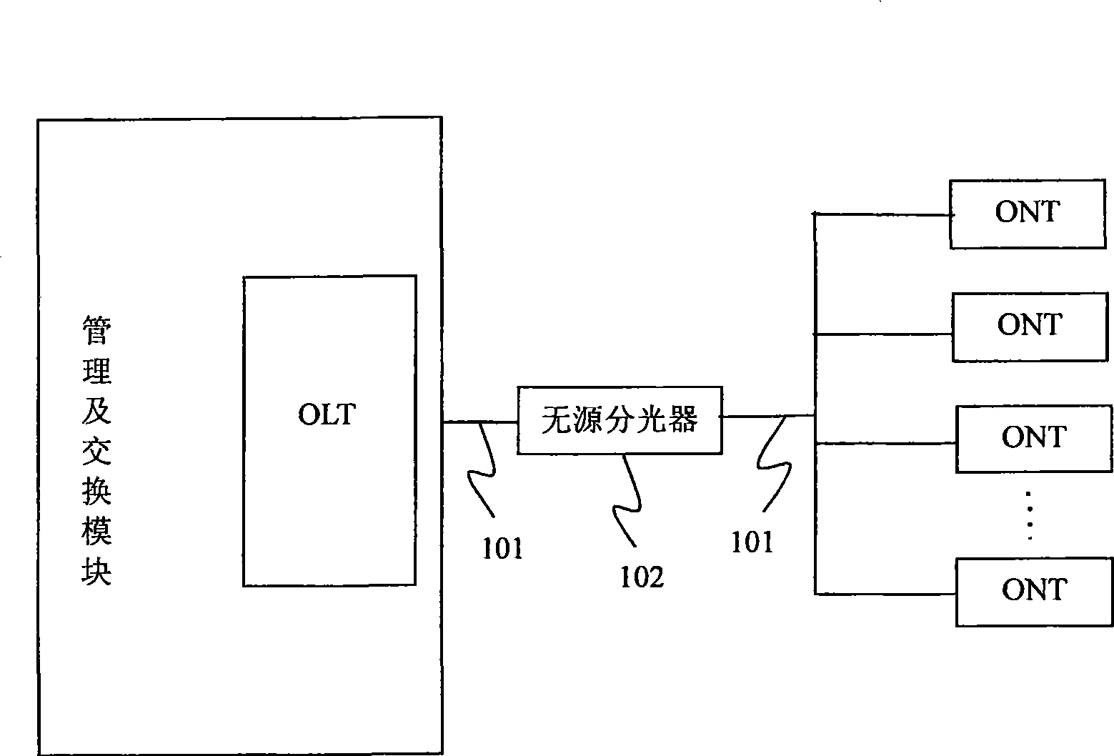
technical field [0001] The invention relates to a broadband communication system, in particular to a device, method and system for data intercommunication between slave nodes in a point-to-multipoint network. Background technique [0002] The broadband communication system mainly includes a point-to-point system and a point-to-multipoint (P2MP, Point to Multipoint) system. Wherein, the point-to-point system mainly refers to: a master node and a single slave node in the system are connected through a physical point-to-point link, such as a digital subscriber line system (DSL, Digital Subscriber Line). The point-to-multipoint system mainly refers to: a master node and multiple slave nodes in the system are connected through a physically multiplexed link, such as a passive optical network (PON, Passive Optical Network) system. [0003] figure 1 It is a schematic structural diagram of a point-to-multipoint PON system in the prior art. The PON system consists of a master stati...

Claims


Application Information

Patent Timeline
Patent Type & Authority Applications(China)
IPC IPC(8): H04Q11/00
Inventor 谭培龙李宏宇
Owner HONOR DEVICE CO LTD
Learn More