
A battery stack arrangement

A battery stacking and battery technology, applied in the direction of flat batteries, secondary batteries, battery pack components, etc., can solve the problems of shell pressure, electrode thickness change, shell cracking, etc.

Active Publication Date: 2009-03-18
NILAR INT AB
View PDF6 Cites 20 Cited by
  • Summary
  • Abstract
  • Description
  • Claims
  • Application Information

AI Technical Summary

Problems solved by technology

However, one problem with all of the disclosed prior art batteries is that during operation the thickness of the electrodes within each battery cell changes and this in turn creates stress on the casing
Due to the stress on the case and the increased internal resistance, the case can subsequently crack and the battery will not function properly

Method used


Image

  • A battery stack arrangement
  • A battery stack arrangement
  • A battery stack arrangement

Examples


Embodiment Construction

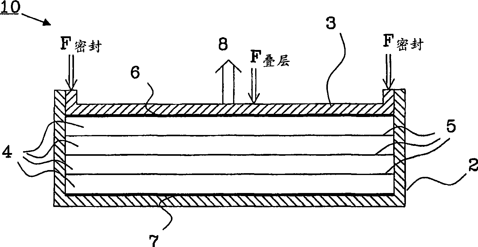
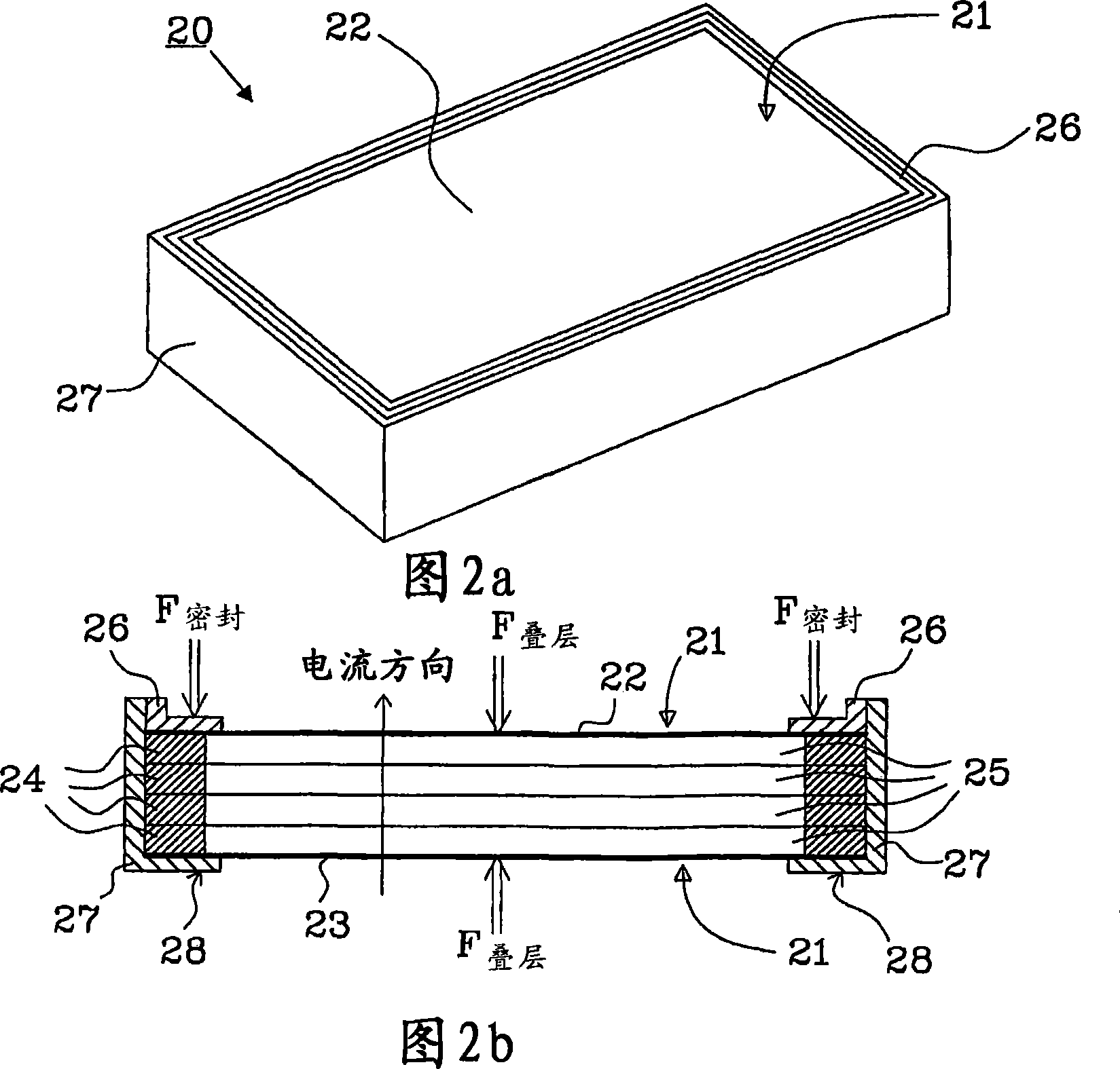
[0019] Each battery cell in a bipolar battery includes a negative electrode and a positive electrode with a spacer in between. Each electrode includes a non-metallic substrate, which makes the electrode inexpensive. Each battery cell is separated from each other by conductive double plates, and positive and negative end plates are arranged on each side of the battery stack, respectively. It is disclosed in the published international patent application WO 03 / 026042 assigned to the applicant that the battery is preferably provided with a common gas space to distribute the pressure in the battery during gas discharge, but the invention can be used with at least one separately arranged battery The unit is implemented in a bipolar battery.

[0020] At the start of the bi-electrode electrical cycle, the cell swells irreversibly. When housed in a rigid case, the expansion of the electrode can generate enormous forces because of the high modulus of elasticity of the electrode itsel...


PUM


Abstract

The present invention relates to a battery stack arrangement (50) comprising at least one bipolar battery. Each bipolar battery comprises a plurality of battery cell arranged between endplates (22,23). Each battery cell is provided with a seal (24) arranged around the entire periphery of each cell, and a sealing pressure Fseal is applied over the seal to prevent electrolyte leakage between adjacent cells. The battery stack arrangement further comprises a mounting frame (57) including: at least two mounting units (58,59) and at least one tie unit (60, 60', 60'') holding said mounting units together. The bipolar battery is arranged between the mounting units (58,59), and the battery stack arrangement further comprises at least one spacing element (61) arranged between the mounting units (58,59) and each spacing element (61) abuts against at least one endplate (22,23) and is held in place by said mounting frame (57) to create a stack pressure Fstack, independent of the sealing pressure Fseal. The stack pressure is controlled by the tie unit.

Description

technical field [0001] The present invention relates to a battery stack device, especially for bipolar batteries for hybrid vehicles. Background technique [0002] An essential feature of the good performance of bipolar batteries of the type disclosed in International Patent Application WO 2005 / 048390 is the low internal resistance between the terminals. This is achieved by applying pressure on multiple battery cells using a hydrophobic seal around the entire perimeter of each battery cell to prevent electrolyte bridges from forming between adjacent battery cells. One disadvantage of prior art batteries is that the amount of pressure applied to the gaskets can be more or less on the laminated elements of the battery cells. In addition, the internal resistance depends on the level of contact that exists between the battery elements and therefore on the magnitude of the mechanical load on the battery stack. The increased pressure will result in a low internal resistance, but...

Claims


Application Information

Patent Timeline
Patent Type & Authority Applications(China)
IPC IPC(8): H01M2/10H01M2/02H01M6/48H01M10/02H01M10/04H01M50/209H01M50/271H01M50/296H01M50/40
CPCY02E60/12H01M10/0413H01M10/0481H01M10/5059H01M6/5038H01M10/5004H01M10/5016H01M10/5032H01M10/0418H01M10/5067H01M10/0468H01M10/5075H01M10/5057H01M2/10H01M10/625H01M10/6563H01M10/647H01M10/6556H01M10/6557H01M10/6567H01M10/613Y02E60/10Y02P70/50H01M50/271H01M50/296H01M50/40H01M50/209
Inventor L·弗雷德里克森N·H·皮斯特R·豪利特
Owner NILAR INT AB
Learn More