

Discharging method for bottom condensate water in volute for fan
An inner bottom, condensate technology, applied in mechanical equipment, machines/engines, liquid fuel engines, etc., can solve the problem of difficult discharge, achieve the effects of small investment, reasonable condensate discharge, and simple transformation
Inactive Publication Date: 2009-03-25
CHINA NON-FERROUS METALS PROCESSING TECH CO LTD
View PDF0 Cites 11 Cited by
- Summary
- Abstract
- Description
- Claims
- Application Information
AI Technical Summary
Problems solved by technology
The discharge of outdoor condensed water not only needs to consider issues such as collection, reuse, and the impact of water quality on the outdoor environment, but also considers the process of discharging the condensed water in the workshop outside the workshop, which will be affected by many internal equipment, pipes, pipe trenches, etc. Influenced by factors, it is more difficult to discharge
Method used
View moreImage
Smart ImageViewing Examples

Examples
Embodiment 1
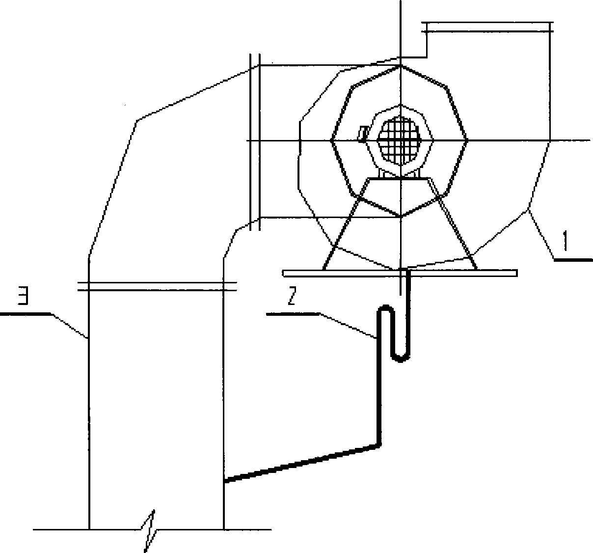
[0013] First install a water trap 2 at the bottom of the volute of the fan 1, the pressure formed by the water seal height of the water trap is greater than the wind pressure in the fan, and then discharge the water from the water trap to the air inlet pipe 3. When the condensed water is generated when the fan discharges steam, humid air or wet waste gas generated on the pool or waste liquid pool upwards, the condensed water can be automatically drained through the water seal and discharged into the air inlet pipe, and finally flow back to the pool. This embodiment does not cause air to flow through here, and also solves the discharge outlet of condensed water.
Login to View More PUM
 Abstract
The invention discloses a discharge method of condensed water in the bottom of a fan volute casing. A trap is arranged on the bottom of the fan volute casing and used as a water seal; pressure from the height of the water seal is higher than wind pressure, so that the condensed water in the volute casing can discharge water automatically through the water seal, without gas mixing, and then the condensed water is refluxed and discharged along the inner wall of an aspiration duct. The discharge method has the advantages of reliable safety of the fan, reasonable, timely and convenient discharge of the condensed water. The discharge method not only avoids motor burnout due to that blades of the fan are hindered by the condensed water but also provides a discharge outlet of the condensed water.
Description
technical field [0001] The invention relates to a method for discharging water in a fan, in particular to a method for discharging condensed water at the inner bottom of a fan volute. Background technique [0002] At present, when the temperature of the gas (steam) body in the fan and the air pipe is gradually reduced during the process of discharging the steam, wet air or wet waste gas and other gas (steam) bodies generated on the pool (or waste liquid pool) upwards by the fan or after the shutdown , will produce condensed water, and the condensed water will stay at the bottom of the volute in the fan, thus submerging the impeller. When the fan is running or restarted, it will cause an accident of burning the motor due to the excessive load of the impeller. Therefore, a drain pipe (with water seal) is often designed at the bottom of the fan to drain the condensed water out of the room. The discharge of outdoor condensed water not only needs to consider issues such as colle...
Claims
Login to View More Application Information
Patent Timeline
 Patent Type & AuthorityApplications(China)
IPC IPC(8): F04D29/00
Inventor冯安朝柴续斌昝笑伟胡保华
OwnerCHINA NON-FERROUS METALS PROCESSING TECH CO LTD