Laminated torsion spring
A laminated, torsion spring technology used in the field of mechanical parts to achieve high flexibility and low discreteness
- Summary
- Abstract
- Description
- Claims
- Application Information
AI Technical Summary
Problems solved by technology
Method used
Image
Examples
Embodiment 1
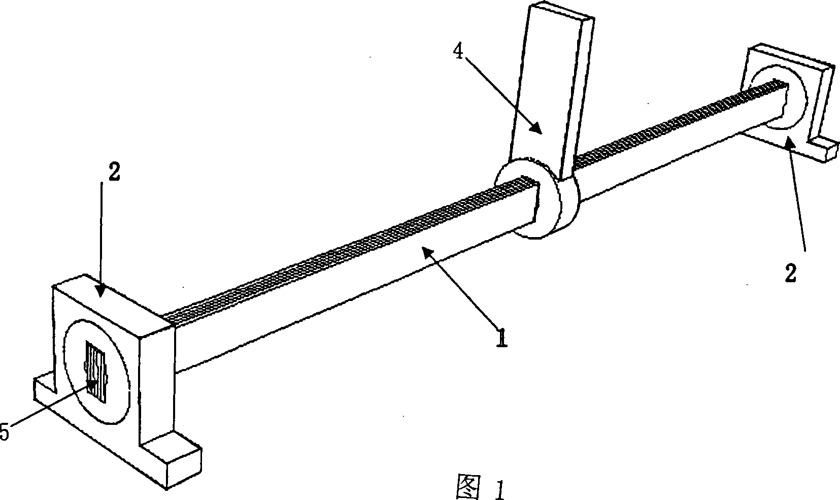
[0021] As shown in Figures 1 and 3.
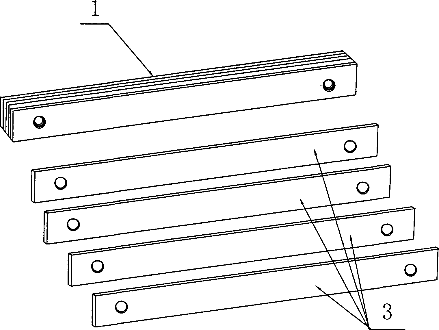
[0022] A laminated torsion spring, which consists of a spring body 1 and a fixing seat 2 installed at both ends of the spring body 1, as shown in Figure 1, the fixing seat 2 is provided with a rectangular or square hole for inserting the end of the spring body 1 , the spring body 1 is formed by stacking two or more thin steel plates 3 with elasticity, the force acting point of the torsion arm 4 in the middle should be located on the center line 5 of the spring body 1, and the two thin steel plates 3 The ends are riveted together by rivets, such as image 3 as shown,
[0023] The torsion action point of the torsion spring in this embodiment is located in the middle section, and the control of the torsion force can be realized by rationally designing the thickness and width of the thin steel plate 3 and adjusting the position of the torsion action point. This embodiment can be used in occasions where the torque is large, the rotation angle...
Embodiment 2
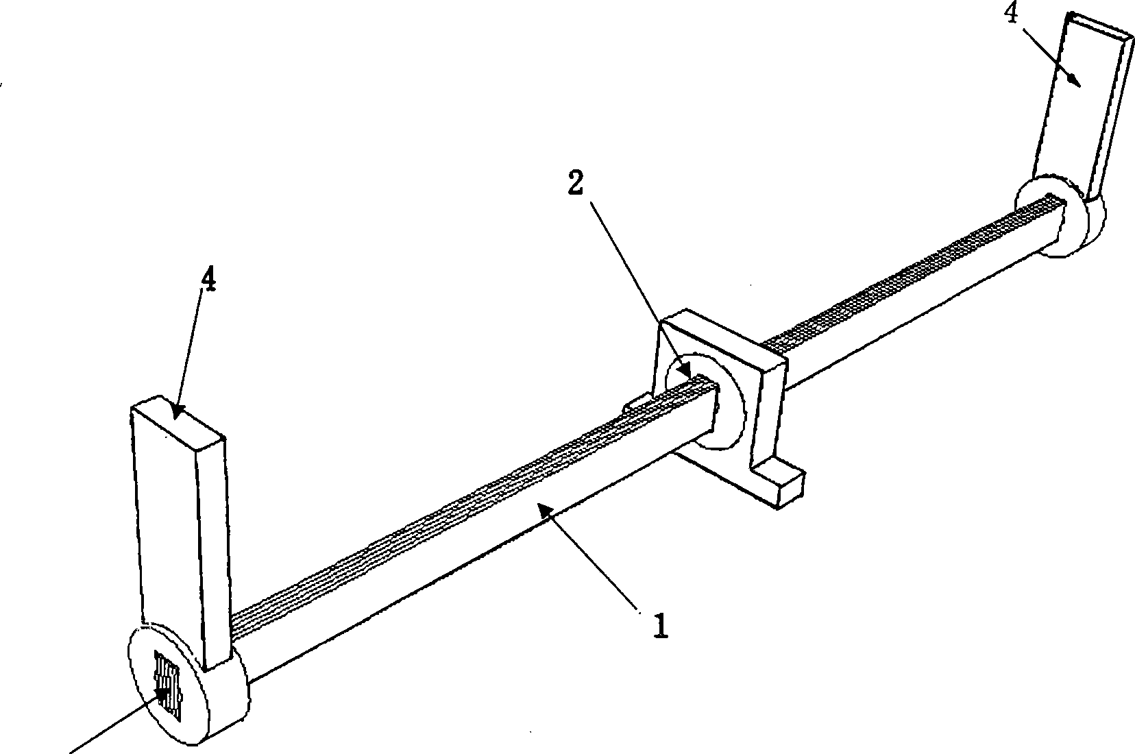
[0025] Such as figure 2 , 3
[0026] A laminated torsion spring, which consists of a spring body 1 and a fixing seat 2 installed on the middle section of the spring body 1, such as figure 2 As shown, the fixed seat 2 is provided with a rectangular or square hole for inserting the spring body 1. The spring body 1 is formed by superimposing two or more elastic thin steel plates 3, and the force of the torsion arms 4 at both ends All points should be located on the center line 5 of the spring body 1 to ensure the linearity, controllability and calibration of the torsion force. The two ends of the thin steel plate 3 are connected by rivets, such as image 3 shown.
[0027] The torsion action point of the torsion spring in this embodiment is located at both ends of the spring member 1, and the control of the torsion force can be realized by rationally designing the thickness and width of the thin steel plate 3 and adjusting the position of the torsion action point. This embodim...
PUM
 Abstract
Description
Claims
Application Information
 - R&D
- Intellectual Property
- Life Sciences
- Materials
- Tech Scout
- Unparalleled Data Quality
- Higher Quality Content
- 60% Fewer Hallucinations
Browse by: Latest US Patents, China's latest patents, Technical Efficacy Thesaurus, Application Domain, Technology Topic, Popular Technical Reports.
© 2025 PatSnap. All rights reserved.Legal|Privacy policy|Modern Slavery Act Transparency Statement|Sitemap|About US| Contact US: help@patsnap.com


