

Distributed finned heat exchanger
A heat exchanger and fin technology, applied in the field of heat dissipation equipment with novel structure, can solve the problems of waste, high energy consumption, waste of material weight, etc.
- Summary
- Abstract
- Description
- Claims
- Application Information
AI Technical Summary
Problems solved by technology
Method used
Image

Examples
Embodiment Construction
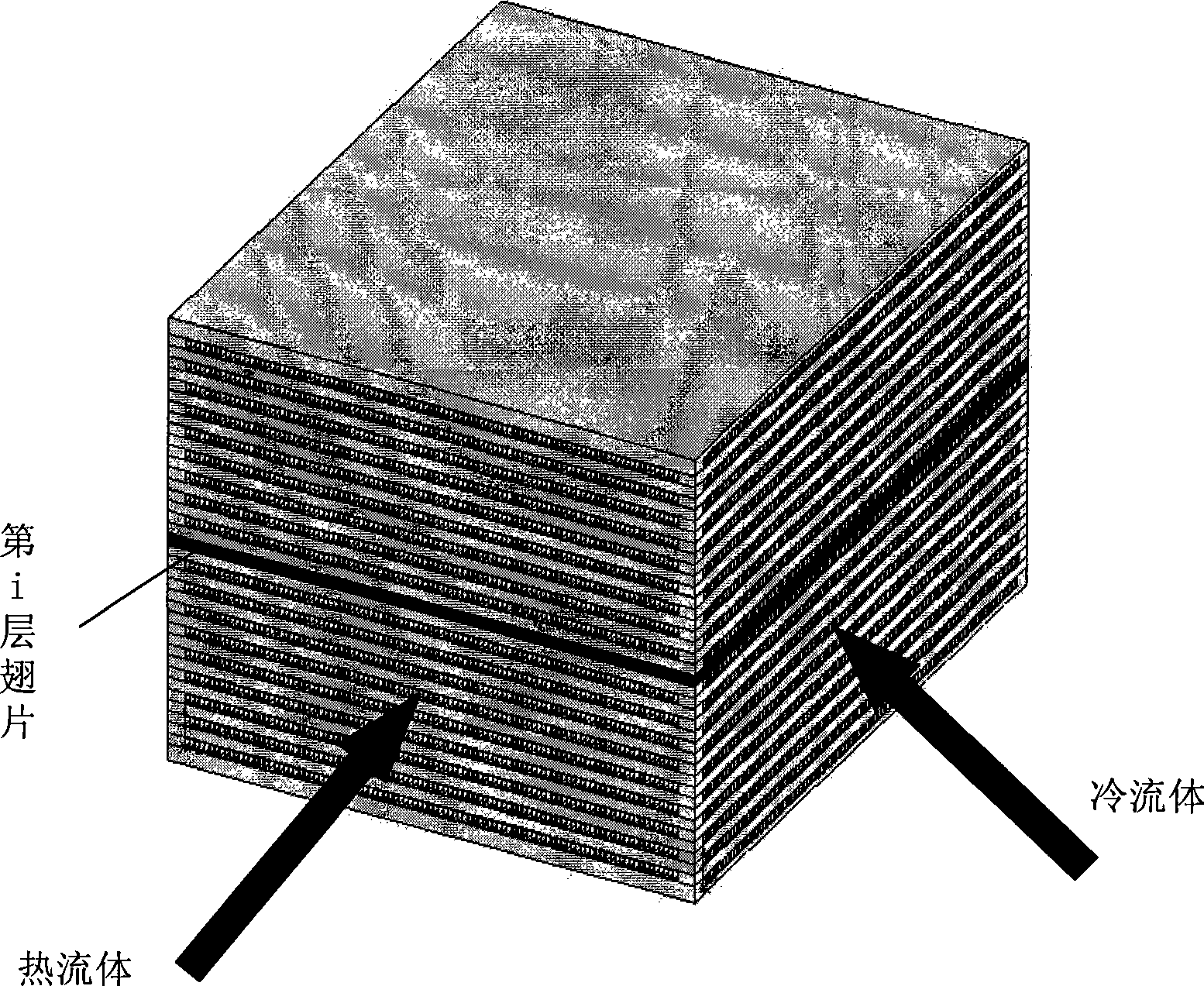
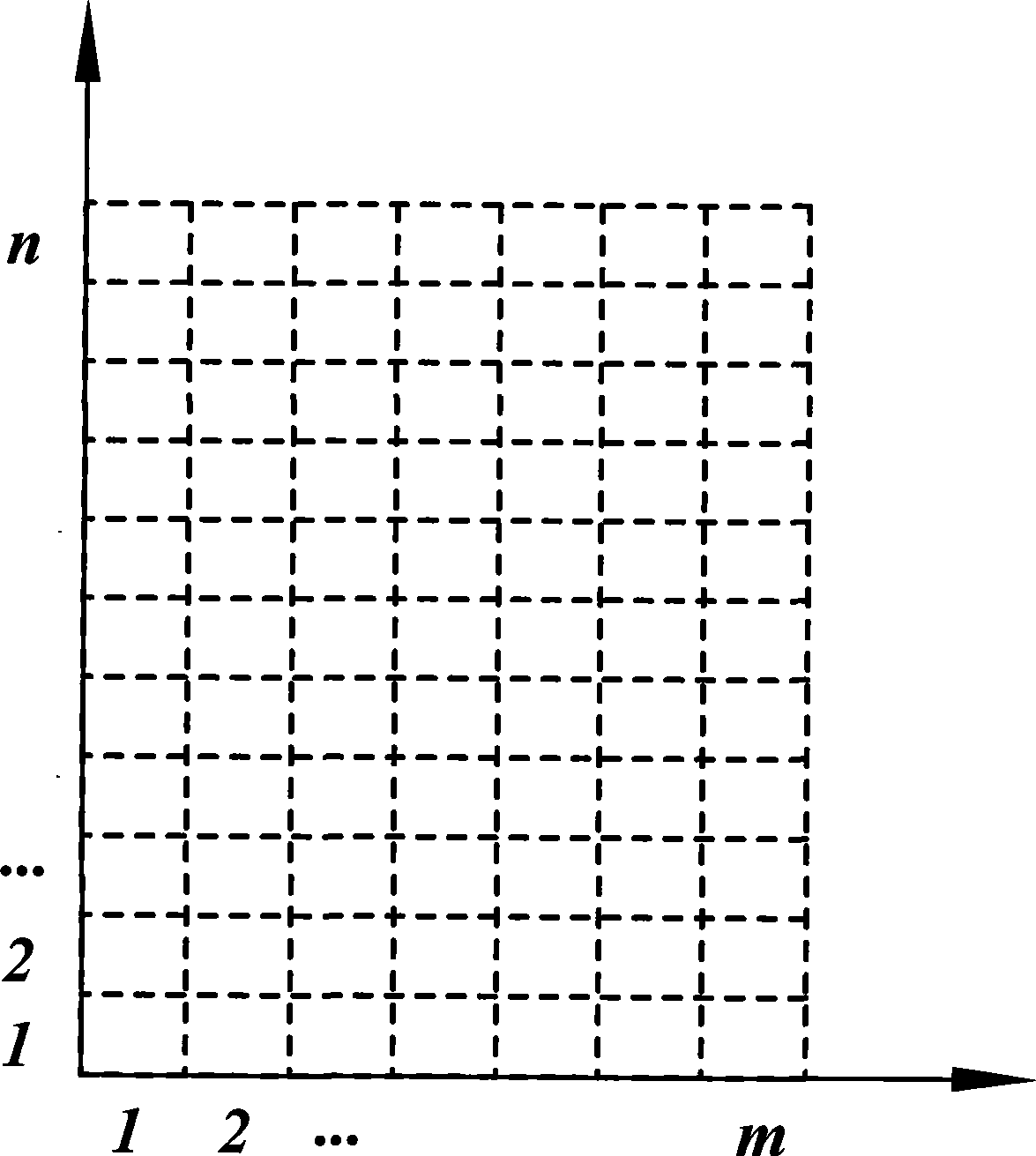
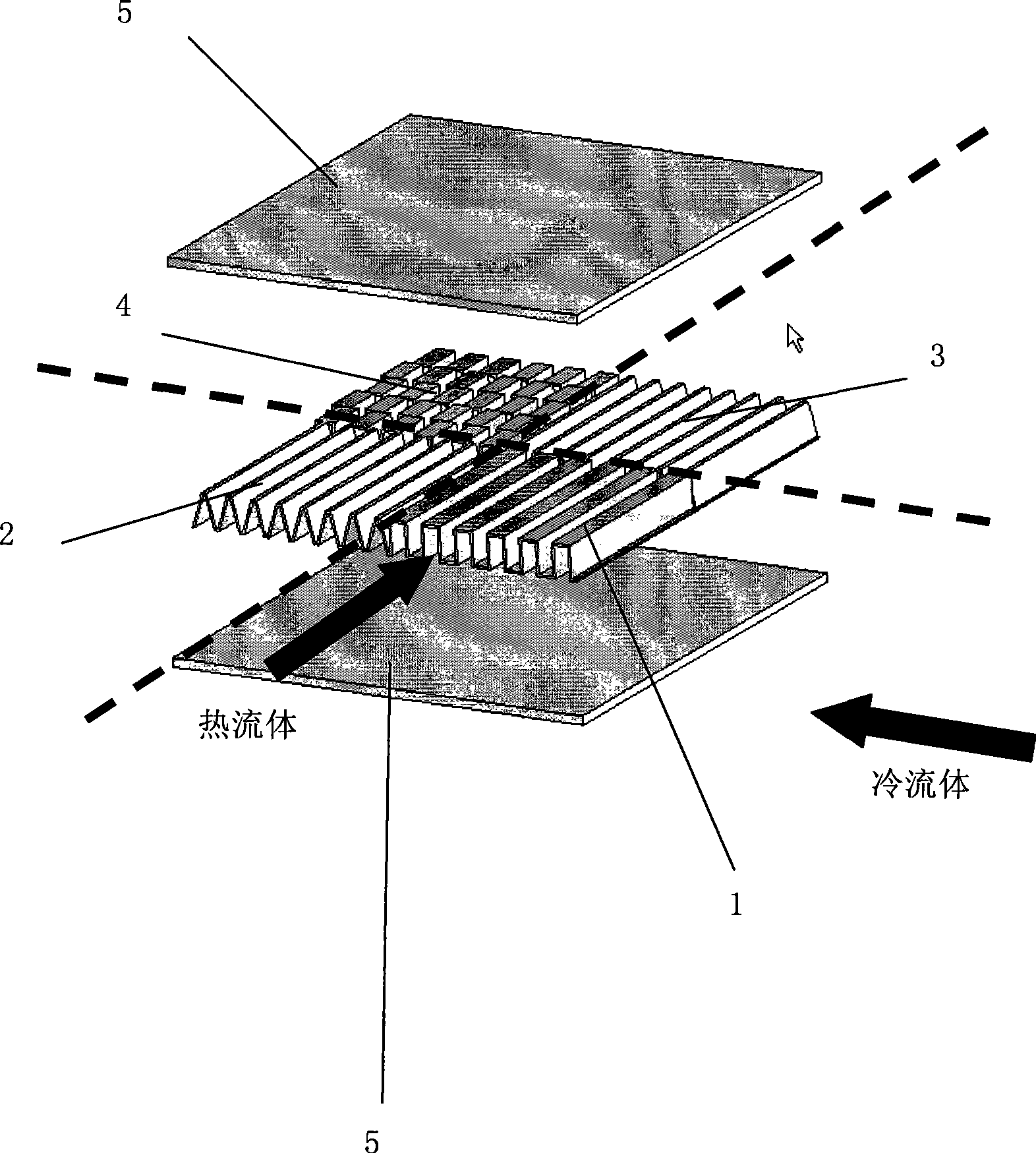
[0018] The present inventor has carried out in-depth research on the design method of the compact heat exchanger, and proposed a new mathematical model—distributed parameter model. The characteristics of this model are: the compact heat exchanger is divided into several micro-element control bodies according to the fin scale, and the distribution of temperature, pressure and other thermal parameters of each micro-element control body is solved by the energy balance equation of the control body . Since the characteristic scale used in the calculation of the mathematical model is equal to the scale of the fins in the physical model of the heat exchanger, compared with the CFD (Computational Fluid Dynamics) method, the physical meaning of the micro-element control body is more clear, and the existing The heat transfer and resistance performance data of the fins, the calculation speed has a breakthrough improvement compared with the CFD method, and the optimal design of the heat e...
PUM
 Abstract
Description
Claims
Application Information