Image processing process for touch screen positioning

An image processing and touch screen technology, applied in electrical digital data processing, input/output process of data processing, instruments, etc., can solve the problems of easy deformation of motion trajectory, slow data collection speed, large positioning error, etc., to speed up the collection speed and refresh speed, image capture in time, and the effect of improving transmission speed

Active Publication Date: 2009-03-25
日照市睿翅电子商务产业有限公司
View PDF0 Cites 12 Cited by
  • Summary
  • Abstract
  • Description
  • Claims
  • Application Information

AI Technical Summary

Problems solved by technology

[0002] In the existing image processing method for touch screen positioning, the connection of multiple image sensors, some in order to reduce costs, through a DSP (digital information processor), MCU (single-chip microcomputer) or FPGA (field programmable gate array) ) is connected with a plurality of image sensors, and the plurality of image sensors adopt asynchronous shooting mode to shoot, and then DSP or MCU or FPGA asynchronously read the captured image data, but this will cause a large positioning error, Especially when the moving speed of the touching object is fast, for example: if the shooting time difference between two image sensors is |t 1 -t 2 |, where t 1 is the time when the first image sensor captures, t 2 is the shooting time of the second image sensor, assuming that the speed of the moving object is v, the position of the moving object changes by v * |t 1 -t 2 |, the faster the speed and the greater the time difference, the greater the calculated positioning error
At present, it is also possible to equip each image sensor with a DSP, MCU or FPGA to realize synchronous shooting and synchronous reading of image data, but this method is very expensive.
[0003] At the same time, the image processing speed of the existing image sensor is limited by the pixel size, and the data acquisition speed is relatively slow, which will cause the trajectory of the fast-moving object on the touch positioning device to be easily deformed.
In fact, the effective pixels needed for touch positioning are only a small part, and a large part of the pixels are wasted

Method used


Image

  • Image processing process for touch screen positioning
  • Image processing process for touch screen positioning
  • Image processing process for touch screen positioning

Examples


Embodiment 1

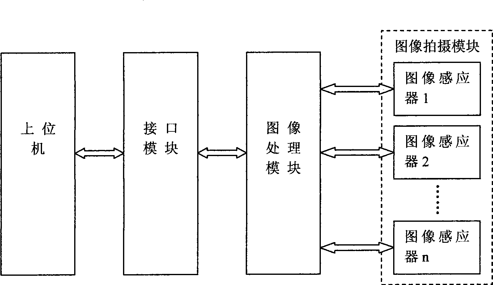
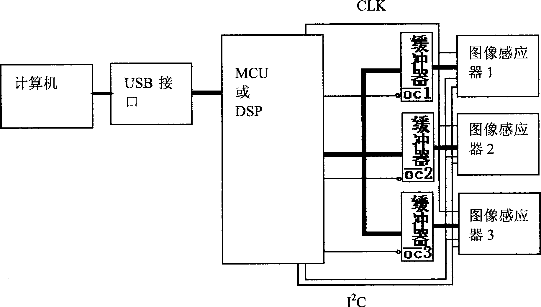
[0033] Such as figure 2 As shown, the upper computer of the present embodiment is a computer, the interface module is a USB interface, the image processing module is a DSP, and the image sensors used are three, and three image sensors are connected between the DSP and the three image sensors. buffer corresponding to the device. The image processing method of the present embodiment includes the following steps:

[0034] (1) DSP through I 2 The C bus initializes and sets the working mode of each image sensor in the image capture module, the synchronous relationship between the image data reading area and the timing of the reference signal, and the output format of the image data.

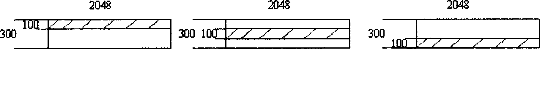
[0035] (2) The three image sensors in the image capture module are synchronously photographed, and the image processing module reads the image data of the output shooting area of ​​the image capture module in time-sharing, and the read part is each image sensor during time-sharing reading. The ima...

Embodiment 2

[0048] The image processing method in this embodiment is the same as that in Embodiment 1, except that the image processing module used is an MCU.


PUM


Abstract

The invention provides an image processing method for positioning a touch screen, which comprises the following steps: firstly, an image shooting module is initialized; secondly, a plurality of image sensors in the image shooting module perform synchronous shooting, and an image processing module performs time-sharing read on image data of effective shooting areas of various image sensors; thirdly, two storage areas the memory spaces of which are both one frame, wherein the other memory space is used for reading out the image data when one memory space is used for writing in the image data, the two memory spaces are alternately transformed and write-in and read-out are simultaneously performed; and fourthly, communication between the image processing module and a host computer is performed, and a position coordinate of a final touch point is determined. The image processing method for positioning the touch screen has the advantages of low cost, high positioning precision and quick transmission speed.

Description

technical field [0001] The invention relates to the technical field of sensor image processing, in particular to an image processing method for touch screen positioning. Background technique [0002] In the existing image processing method for touch screen positioning, the connection of multiple image sensors, some in order to reduce costs, through a DSP (digital information processor), MCU (single-chip microcomputer) or FPGA (field programmable gate array) ) is connected with a plurality of image sensors, and the plurality of image sensors adopt asynchronous shooting mode to shoot, and then DSP or MCU or FPGA asynchronously read the captured image data, but this will cause a large positioning error, Especially when the moving speed of the touching object is fast, for example: if the shooting time difference between two image sensors is |t 1 -t 2 |, where t 1 is the time when the first image sensor captures, t 2 is the shooting time of the second image sensor, assuming t...

Claims


Application Information

Patent Timeline
Patent Type & Authority Applications(China)
IPC IPC(8): G06F3/041
Inventor 卢如西钟杰婷
Owner 日照市睿翅电子商务产业有限公司
Why Eureka
Try Eureka