
View field driving real-time shadow method

A field of view and shadow technology, applied in 3D image processing, image data processing, instruments, etc., can solve problems such as the influence of shadow drawing speed, and achieve the effect of improved effect, good effect, and improved utilization rate

Inactive Publication Date: 2009-03-25
BEIHANG UNIV
View PDF0 Cites 15 Cited by
  • Summary
  • Abstract
  • Description
  • Claims
  • Application Information

AI Technical Summary

Problems solved by technology

This method, like QVSM and FVSM, needs to draw multiple shadow maps, and the speed of shadow drawing is affected

Method used


Image

  • View field driving real-time shadow method
  • View field driving real-time shadow method
  • View field driving real-time shadow method

Examples


Embodiment Construction

[0031] Such as Figure 5 Shown, the concrete realization steps of the present invention are as follows:

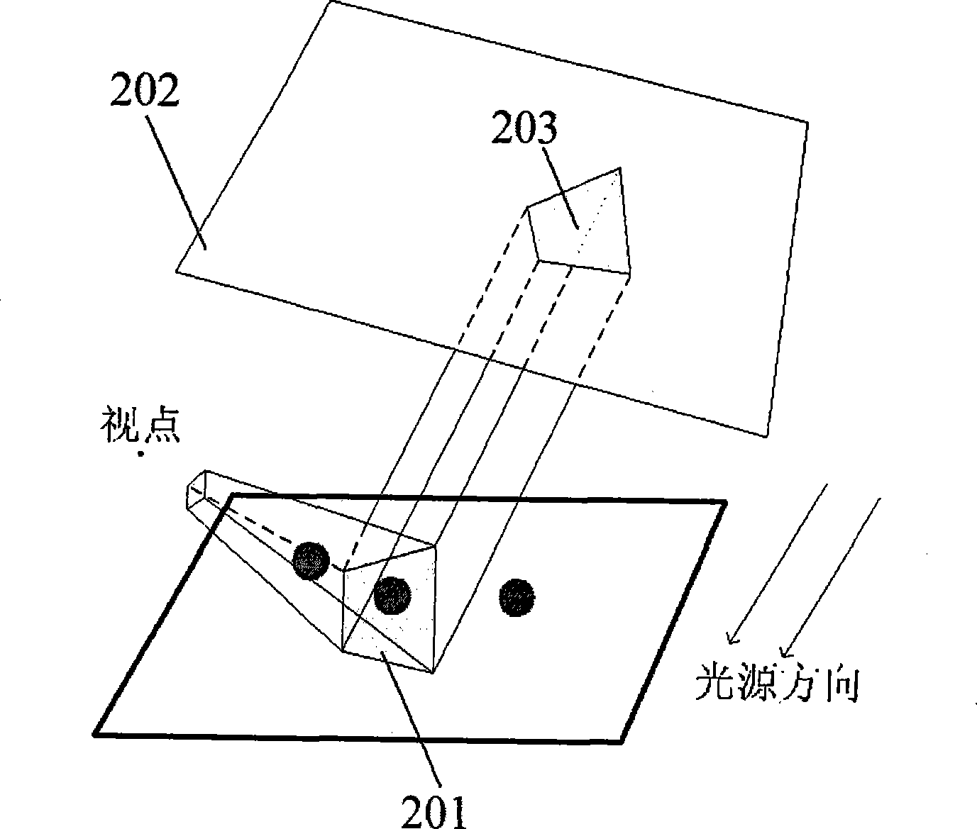
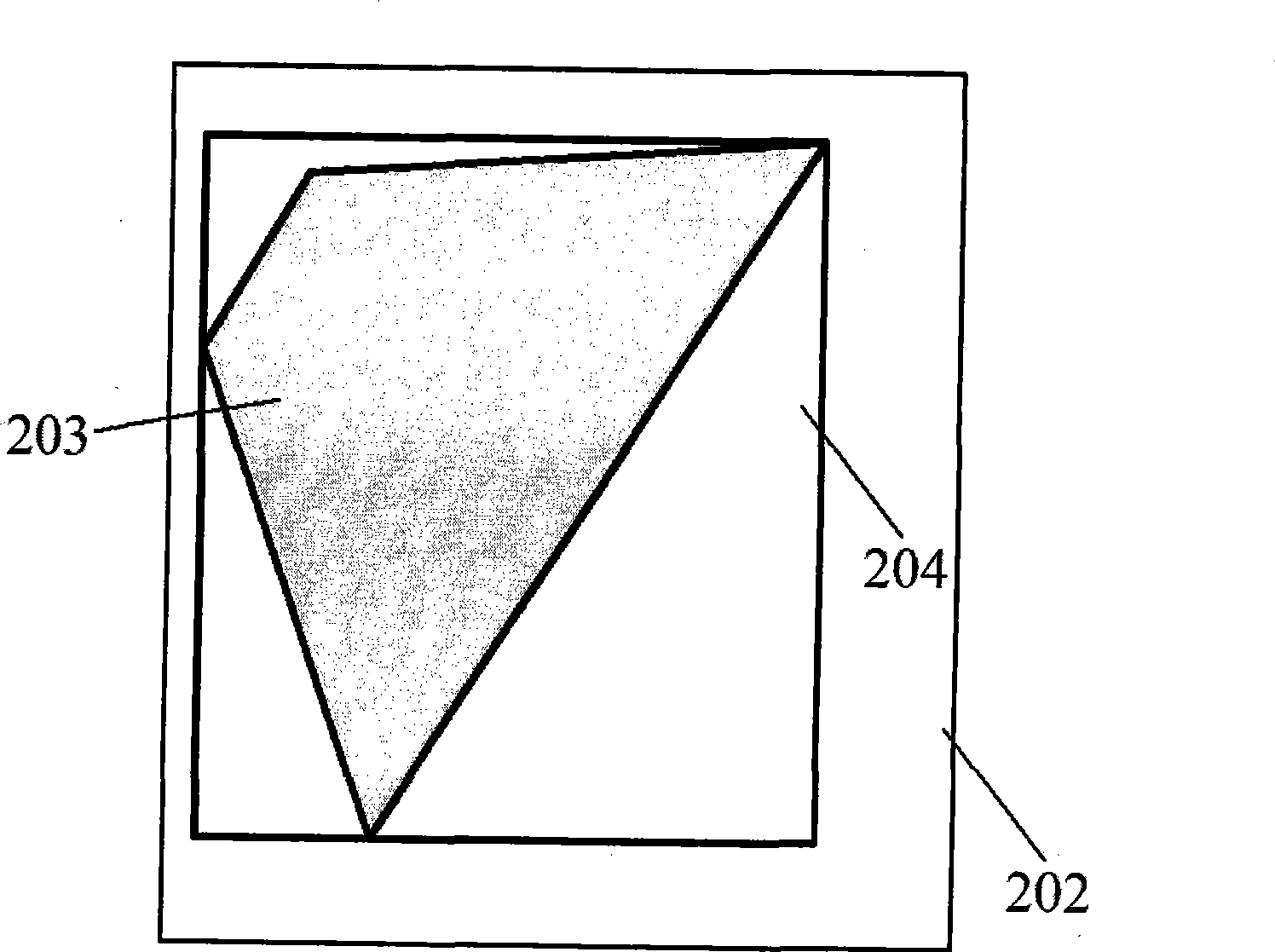
[0032] Step S501 , in step S501 , back-project the field of view 201 onto the light source plane 202 , and generate a two-dimensional AABB bounding box 204 for the field of view 201 on the light source plane 202 .

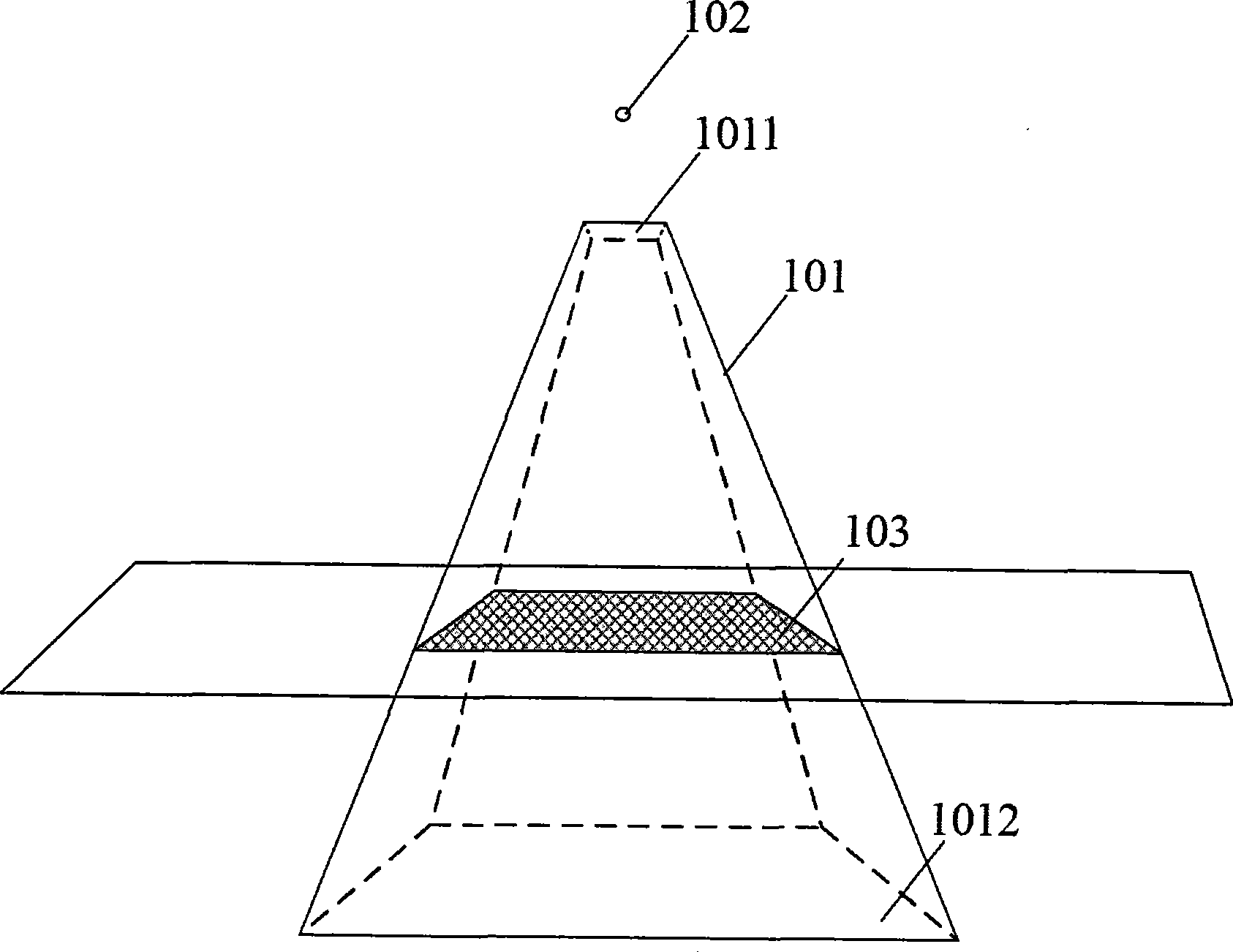
[0033] The field of view in the present invention is different from the viewing frustum, and refers to the range of the shadow receiver that can be seen from the viewpoint position. figure 1 Indicates the difference between the field of view and the viewing frustum. The viewing frustum 101 is a standard viewing frustum concept in graphics, determined by the projection transformation matrix, and the depth range extends from the front clipping plane 1011 to the rear clipping plane 1012. The field of view 103 in the present invention refers to the farthest range in the scene that can be seen by the viewpoint 102. figure 1 marked with grid lines.

[0034] Since ...


PUM


Abstract

The invention relates to a method for real-time shadow driven by field of view. In a three-dimensional virtual environment, the method adopts the following steps: firstly, the field of view is projected to the plane of a light source to generate a projection area, and generate a two-dimensional AABB bounding box for the projection area; secondly, a shadowgraph is generated, and the range of coverage of the shadowgraph is only within the AABB bounding box; and thirdly, the shadowgraph is mapped into a scene to generate shadow. The invention has the advantages that unnecessary shadow drawing in the scene is avoided, the utilization factor of the shadowgraph is increased, and the anti-aliasing effect is very good; in addition, only one to two shadowgraphs need to be drawn, and the real-time property is very high, thereby meeting the requirement of real-time shadow drawing in a large-scale scene with millions of patches.

Description

technical field [0001] The invention relates to a real-time shadow method in a three-dimensional virtual environment, in particular to a field-of-view-driven real-time shadow method. Background technique [0002] In the real-time shadow rendering method based on the shadow map currently studied, the research methods for the classic shadow map method shadow applied to the shadow aliasing problem in scene rendering are mainly divided into two categories. The first category is based on Perspective Shadow Maps (PSM). These methods are anti-aliased by reparameterizing the shadow map. Another type of method is based on Adaptive Shadow Maps (ASM). The basic idea of ​​this type of method is to improve the resolution of the shadow map to achieve the purpose of anti-aliasing. [0003] The PSM method transforms both the scene and light sources into the post-projection space and generates shadow maps. Through the transformation, objects closer to the viewpoint are enlarged, and object...

Claims


Application Information

Patent Timeline
IPC IPC(8): G06T15/60
Inventor 沈旭昆齐越胡勋
Owner BEIHANG UNIV
Learn More