Isolation transmitter for field bus

A field bus and transmitter technology, which is applied in line transmission parts, bus network, data exchange through path configuration, etc., can solve problems such as easy failure and inconvenient communication.

Active Publication Date: 2011-05-11
CHENGDU HANGTIAN PHOTOELECTRIC TECH
View PDF3 Cites 0 Cited by
  • Summary
  • Abstract
  • Description
  • Claims
  • Application Information

AI Technical Summary

Problems solved by technology

[0009] The purpose of the present invention is to solve the problem that existing bus isolation transmitters are not convenient and prone to failure due to the use of cascaded buffers and / or directional structures, and provide an innovative field bus isolator that has electrical isolation In addition to the bus signal enhancement function, it also has the signal bidirectional transmission function, transparent transmission function, bit-by-bit contention transmission function, and bus protection function

Method used


Image

  • Isolation transmitter for field bus
  • Isolation transmitter for field bus
  • Isolation transmitter for field bus

Examples


Embodiment Construction

[0035] The present invention will be further described below in conjunction with specific embodiments and drawings.

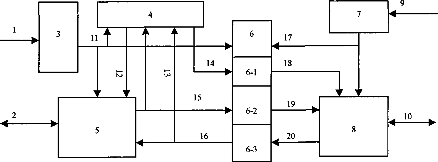
[0036] Such as figure 2 As shown, the fieldbus isolation transmitter includes:

[0037] The first isolated power converter 3 connected to the first bus power source 1, the second isolated power converter 7 connected to the second bus power source 9; the first signal bus identification and driver 5 connected to the first signal bus 2, and The second signal bus identification and driver 8 connected to the second signal bus 10; the control circuit 4 connected to the first isolated power converter 3, the first signal bus identification and driver 5, and the photocoupler 6; the photocoupler 6 and the first signal bus An isolated power converter 3, a first signal bus identification and driver 5, a second isolated power converter 7, and a second signal bus identification and driver 8 are connected.

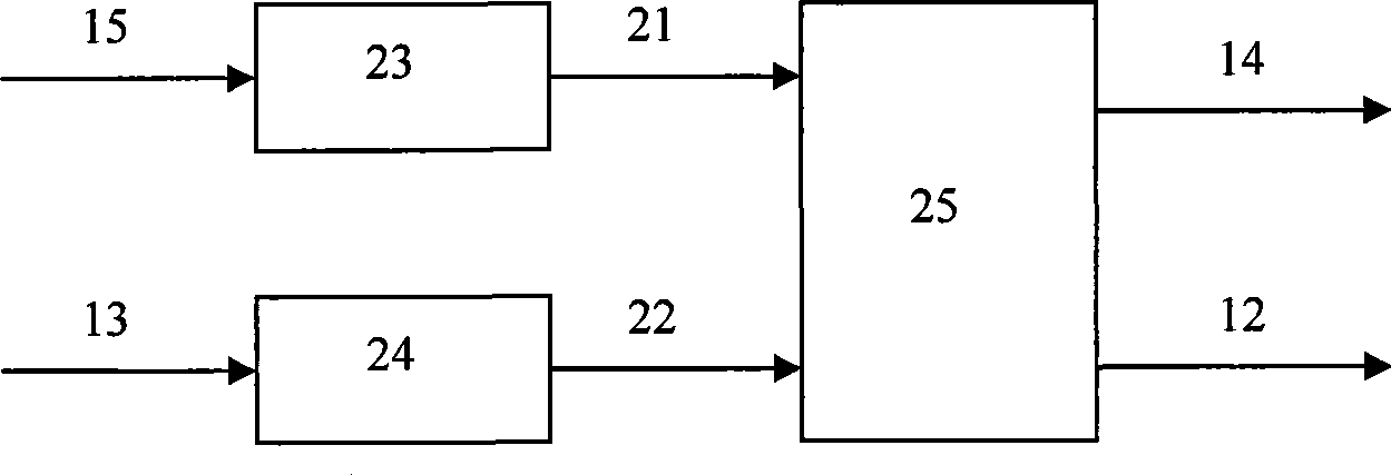
[0038] Such as image 3 As shown, the above-mentioned control circuit 4 i...


PUM


Abstract

A field bus isolation transmitter relates to an isolation transmitter with electric isolation and signal transmission functions and used for buses of an electric control system. The isolation transmitter aims to solve the problems of the prior bus isolation transmitter, such as inconvenient communication and high possibility of faults due to the adoption of cascade buffer and / or the existence of a directional structure. The isolation transmitter comprises a first isolation power converter connected with a first bus power supply, a second power converter connected with a second bus power supply, a first signal bus identifier and driver connected with a first signal bus, a second signal bus identifier and driver connected with a second signal bus, and a control circuit connected with the first isolation power converter, the first signal bus identifier and driver and a photoelectric coupler, wherein the photoelectric coupler is connected with the first isolation power converter, the first signal identifier and driver, the second isolation power converter and the second signal identifier and driver.

Description

Technical field [0001] The invention relates to an isolated transmitter with electrical isolation and signal transmission functions for a bus applied to an electrical control system. Background technique [0002] In an electrical control system, multiple electronic devices communicate via fieldbus. These electronic devices are distributed far away from each other and use distributed power supply. [0003] Due to the use of distributed power supply, the electrical reference points (signal grounds) between the various electronic devices are inconsistent, and it is necessary to electrically isolate the signal bus from the bus power supply. [0004] However, the remotely distributed arrangement makes the communication signal between various electronic devices attenuate greatly, and the communication is unstable. Signal relay transmission is required to improve the reliability of signal transmission. [0005] Therefore, in the process of transmitting electrical signals on the bus, in order...

Claims


Application Information

Patent Timeline
Patent Type & Authority Patents(China)
IPC IPC(8): H04L25/02H04L12/40H04B3/02
Inventor 郑旭东庞季洪姚志生张波
Owner CHENGDU HANGTIAN PHOTOELECTRIC TECH
Why Eureka
Try Eureka