An isolated low current ripple high gain DC converter and its control method

A technology of DC converter and isolation transformer, which is applied in the direction of converting DC power input to DC power output, adjusting electrical variables, and controlling/regulating systems. It can solve the problem of high voltage stress of switching devices, increased voltage stress of switching tubes or diodes, and transformer Obvious problems such as parasitic effects, to achieve the effect of small input current ripple

Active Publication Date: 2020-10-09
FUZHOU UNIV
View PDF5 Cites 0 Cited by
  • Summary
  • Abstract
  • Description
  • Claims
  • Application Information

AI Technical Summary

Problems solved by technology

[0003] The traditional isolated DC converter realizes various boosting functions by adjusting the transformation ratio of the transformer. However, the following problems exist in obtaining high gain simply by using a transformer with a high turn ratio: the voltage stress of the switching device is high, and the leakage inductance of the transformer causes The voltage spike and oscillation will increase the voltage stress of the switching tube or diode, reduce the reliability and efficiency, and cause serious electromagnetic interference problems, and the parasitic effect of the transformer with high turns ratio is obvious, and the design is difficult, etc.
Therefore, simply using high-turn ratio transformers or coupled inductors to obtain high gains has great limitations.

Method used


Image

  • An isolated low current ripple high gain DC converter and its control method
  • An isolated low current ripple high gain DC converter and its control method
  • An isolated low current ripple high gain DC converter and its control method

Examples


Embodiment Construction

[0030] The technical solution of the present invention will be specifically described below in conjunction with the accompanying drawings.

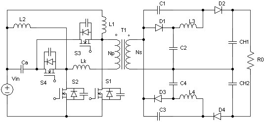
[0031] Such as figure 1As shown, the present invention provides an isolated low-current ripple high-gain DC converter, including a DC input power supply, an isolation transformer with leakage inductance, a first switch tube, a second switch tube, a third switch tube, and a fourth switch tube. Tube, first diode, second diode, third diode, fourth diode, first inductance, second inductance, third inductance, fourth inductance, first capacitor, second capacitor, The third capacitor, the fourth capacitor, the fifth capacitor, the sixth capacitor, the seventh capacitor and the load; the positive pole of the DC input power supply is connected to one end of the seventh capacitor, one end of the second inductor, and one end of the first inductor, and the DC input power supply The negative pole of the first switch tube is connected to one end of t...


PUM


Abstract

The invention relates to an isolated low-current ripple high-gain direct-current converter and a control method thereof. The isolated low-current ripple high-gain direct-current converter comprises adirect-current input power supply, the circuit comprises an isolation transformer, a first switching tube, a second switching tube, a third switching tube, a fourth switching tube, a first diode, a second diode, a third diode, a fourth diode, a first inductor, a second inductor, a third inductor, a fourth inductor, a first capacitor, a second capacitor, a third capacitor, a fourth capacitor, a fifth capacitor, a sixth capacitor, a seventh capacitor and a load. According to the high-gain direct-current converter, an interleaved Boost converter, the transformer transformation ratio boosting network, the LCD boosting network and the clamping circuit are combined; the converter has the advantages of electrical isolation, high step-up ratio, small input current ripple, small switching device voltage stress, high conversion efficiency and the like, and is very suitable for high-step-up-ratio direct-current voltage conversion application occasions.

Description

technical field [0001] The invention belongs to the technical field of power electronics, and in particular relates to an isolated low-current ripple high-gain DC converter and a control method thereof. Background technique [0002] In the renewable energy power generation system, since the electric energy generated by many renewable energy sources is low-voltage direct current, and the grid-connected power generation system requires a high-voltage DC bus, it needs to be connected between the renewable energy output terminal and the DC bus. Insert a high-gain DC-DC converter to convert low-voltage DC to high-voltage DC suitable for grid connection. Therefore, high-gain, high-efficiency DC-DC converters have attracted more and more attention from domestic and foreign researchers. [0003] The traditional isolated DC converter realizes various boosting functions by adjusting the transformation ratio of the transformer. However, the following problems exist in obtaining high g...

Claims


Application Information

Patent Timeline
Patent Type & Authority Patents(China)
IPC IPC(8): H02M3/335H02M1/14
CPCH02M1/14H02M3/33523Y02B70/10
Inventor 林国庆林思圻
Owner FUZHOU UNIV
Why Eureka
Try Eureka