An endoscope system

A technology of endoscopes and components, applied in the field of endoscope systems, can solve problems such as low signal transmission speed and poor anti-interference ability, and achieve the effects of preventing electrical risks, easy cleaning, and realizing electrical isolation

Active Publication Date: 2018-09-14
PEKING UNIV +1
View PDF6 Cites 0 Cited by
  • Summary
  • Abstract
  • Description
  • Claims
  • Application Information

AI Technical Summary

Problems solved by technology

There are still some deficiencies in the endoscope isolation unit technology described above. The picture quality of the endoscope image is getting better and better, and the signal bandwidth requirements are getting higher and higher. In the above method, the signal transmission speed is low and the anti-interference ability The poor problem is getting worse

Method used


Image

  • An endoscope system
  • An endoscope system
  • An endoscope system

Examples


Embodiment 1

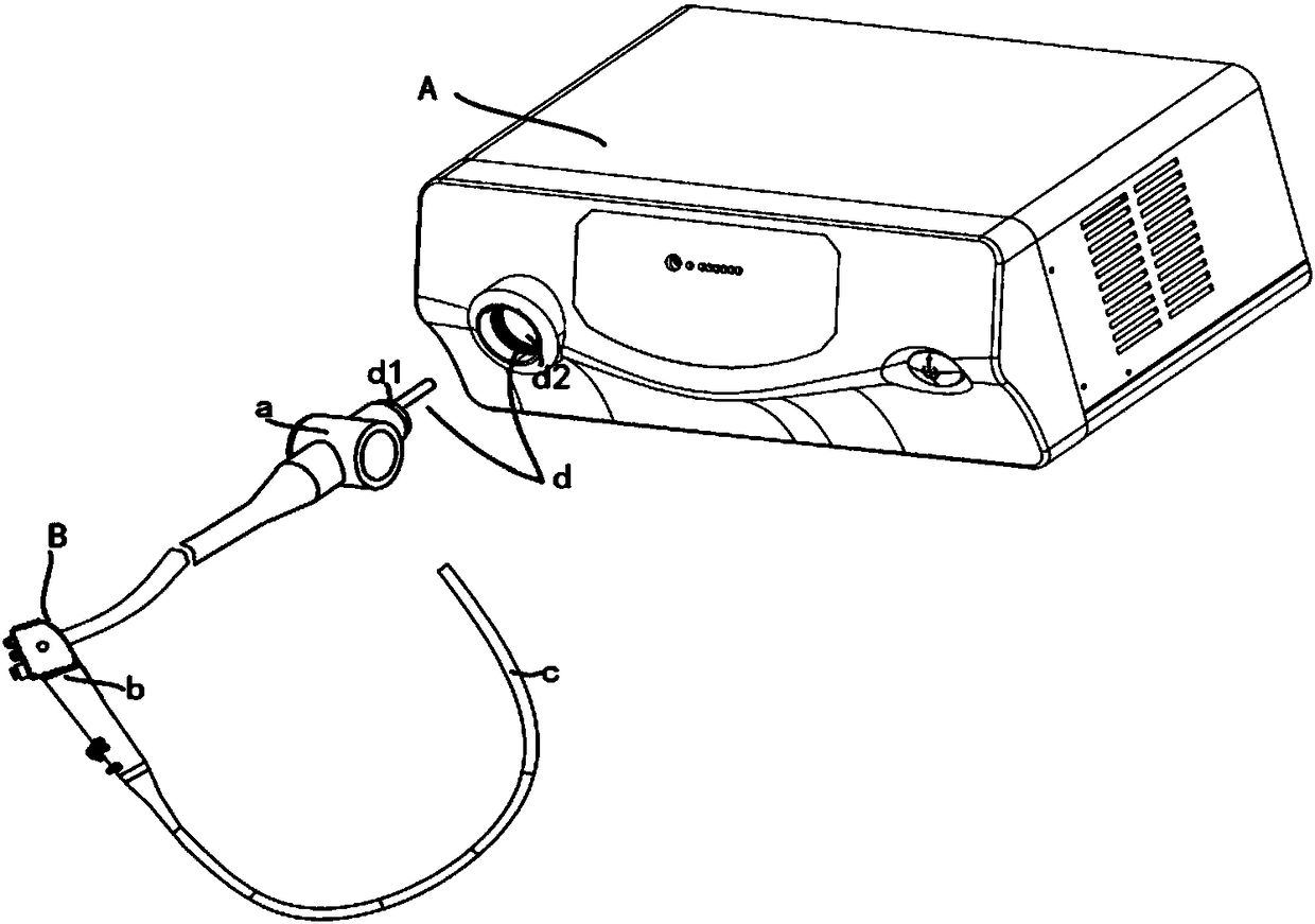
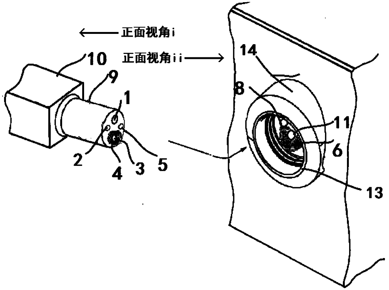
[0063] Such as Figure 2 ~ Figure 4 As shown, the installation position of the electrical isolation unit d in this embodiment 1 is figure 1 In the place d shown, the end of the plug part a is the plug part main body 9, and the end part of the socket part is the socket part main body 13, and the plug part main body 9 and the socket part main body 13 are provided correspondingly, so as to ensure that when the plug part a is inserted into the socket part, The plug body 9 can be correspondingly inserted into the socket body 13 .

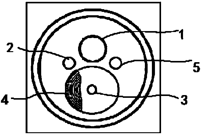
[0064] End face of main body of plug part d 1 It is circular, on which energy and signal transmission components are installed, that is, light source light receiving component 1, low-speed signal receiving component 5, gas inlet component 2, laser signal sending component 3 and wireless energy receiving component 4; among them, wireless energy receiving component 4 The wireless power transmission receiving coil and the magnetic isolation material are h...

Embodiment 2

[0067] Such as Figure 5 ~ Figure 6 As shown, the installation position of the electrical isolation unit d in Example 2 is figure 1 At the point d shown, the end face of the main body of the plug part d 1 There are four units, among which: unit ① is equipped with wireless energy receiving component 4, unit ② is equipped with low-speed signal receiving component 5, unit ③ is equipped with laser signal sending component 3, unit ④ is equipped with light source light receiving component 1 and air inlet component 2. End face of socket part d 2 Upper mounting and plug main body end face d 1 on the corresponding energy and signal transmission components, and with the end face d 1 The position of the energy and signal transmission components on the mirror is symmetrical, so that when the main body of the plug part 9 is inserted into the main body of the socket part 13, the sending and receiving parts of all transmission components can be closely attached on the end faces, and the a...

Embodiment 3

[0069] Such as Figure 7 ~ Figure 9 As shown, the installation position of the electrical isolation unit d in Embodiment 3 is figure 1 At the point d shown, the end face of the main body of the plug part d 1 It is ellipse, end face d 1 Half side is installed with light source light receiving component 1, low speed signal receiving component 5, air inlet component 2, and laser signal sending component 3, end face d 1 Install the wireless energy receiving component 4 on the other half; the end face of the socket part d 2 Upper mounting and plug body end face d 1 on the corresponding energy and signal transmission components, and with the end face d1 The position of the energy and signal transmission components on the mirror is symmetrical, so that when the main body 9 of the endoscope plug part is inserted into the main body 13 of the socket part of the endoscope, the two parts of the sending and receiving parts of all transmission components can be closely attached on the en...


PUM


Abstract

The invention relates to the technical field of wireless energy transmission equipment and laser signal transmission equipment, and particularly relates to an endoscope system. In the endoscope system, the plug part and the socket part of an electrical isolation unit are respectively correspondingly arranged on an endoscope and a control device, and the plug part can be plugged in the socket part correspondingly; the plug part comprises a laser signal transmission component and a wireless energy receiving component which are arranged in a sealed isolation manner, and the socket part comprises a laser signal receiving component and a wireless energy transmission component which are arranged in a sealed isolation manner. According to the endoscope system, short-range isolated power transmission is realized by utilizing a wireless power transmission technology; and high-speed signal transmission is realized by utilizing a high-speed laser signal transmission technology. The system has high structure integration level, can be applied to an endoscope to realize electrical isolation between the endoscope and the outside, has relatively strong interference resistance, and can be used for effectively stopping electrical risk occurring in application.

Description

technical field [0001] The invention relates to the technical field of wireless energy transmission equipment and laser signal transmission equipment, in particular to an endoscope system. Background technique [0002] Endoscope is a detection instrument that integrates traditional optics, ergonomics, precision machinery, modern electronics, mathematics, and software. It has image sensors, optical lenses, light source lighting, and water vapor control. It can enter the stomach or Enter the body through other natural channels, and use the endoscope to see lesions that cannot be displayed by other medical equipment such as X-rays. [0003] At present, the existing endoscope system uses electrical connection between the endoscope and the control device to realize the transmission of signal and energy, because the stability of signal and energy transmission will decrease with the increase of the number of plugging and unplugging of the electrical connection unit , when the endo...

Claims


Application Information

Patent Timeline
Patent Type & Authority Patents(China)
IPC IPC(8): A61B1/00
CPCA61B1/00013A61B1/00029
Inventor 谢天宇杨春
Owner PEKING UNIV
Why Eureka
Try Eureka