In-wheel motor drive unit

A driving device and motor technology, applied in the direction of gear transmission, power device, transmission, etc., can solve the problems of increase in weight and size of the reducer, inappropriateness, and difficulty in compacting, and achieve the effect of large transmission torque

Inactive Publication Date: 2009-03-25
NTN CORP
View PDF3 Cites 20 Cited by
  • Summary
  • Abstract
  • Description
  • Claims
  • Application Information

AI Technical Summary

Problems solved by technology

This leads to an increase in the weight and size of the reducer, which is not suitable for an in-wheel motor drive device that requires compactness
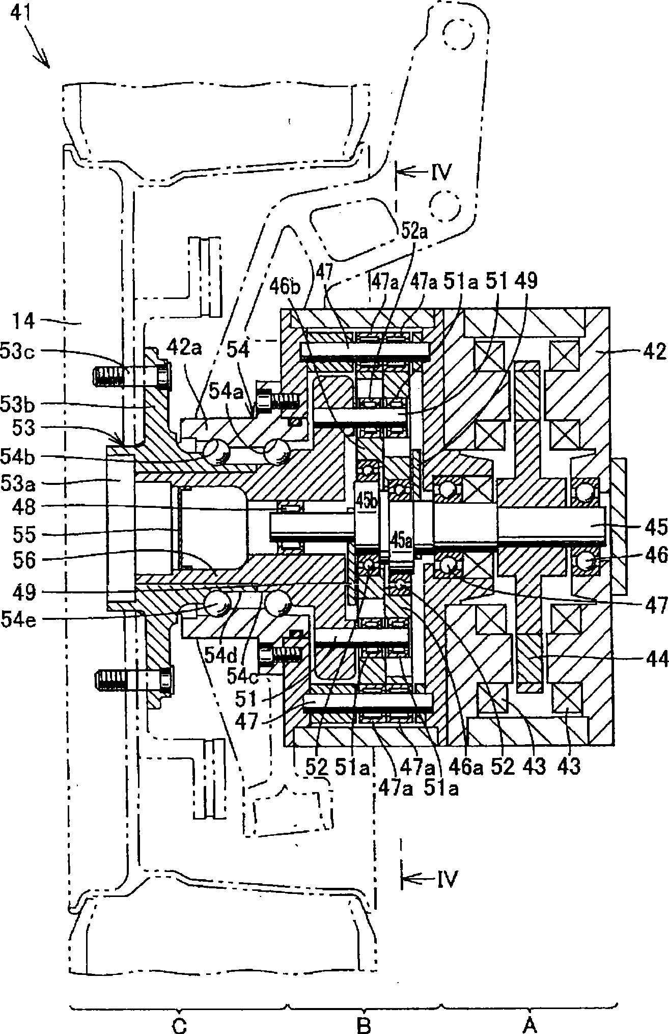
[0014] In addition, the planetary gear reducer can obtain a large reduction ratio compared with the parallel shaft gear, but the planetary gear reducer is composed of a sun gear, a ring gear, a pinion, and a pinion frame, so the number of parts is large, and it is difficult to compact

Method used


Image

  • In-wheel motor drive unit
  • In-wheel motor drive unit
  • In-wheel motor drive unit

Examples


Embodiment Construction

[0042] Referring to Figure 11 and Figure 12 An electric vehicle 11 including an in-wheel motor drive unit (in-wheel motor drive unit) according to an embodiment of the present invention will be described. In addition, FIG. 11 is a top view of an electric vehicle 11, Figure 12 It is the figure which looked at the electric vehicle 11 from the rear.

[0043] Referring to Figure 11 and Figure 12 An electric vehicle 11 has a chassis 12, front wheels 13 as guide wheels, rear wheels 14 as drive wheels, and in-wheel motor drive devices 15 that transmit driving force to the left and right rear wheels 14, respectively. rear wheel 14 as Figure 12 As shown, it is accommodated inside the wheel housing 12a of the chassis 12, and is fixed to the lower part of the chassis 12 via a suspension device (suspension) 12b.

[0044] The suspension device 12b supports the rear wheels 14 by suspension arms extending left and right, and absorbs vibrations received by the rear wheels 14 from the ...


PUM


Abstract

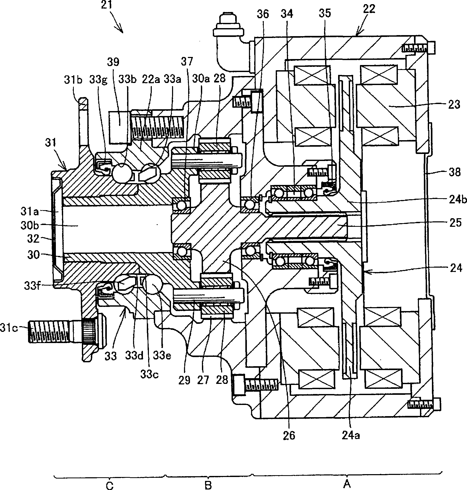
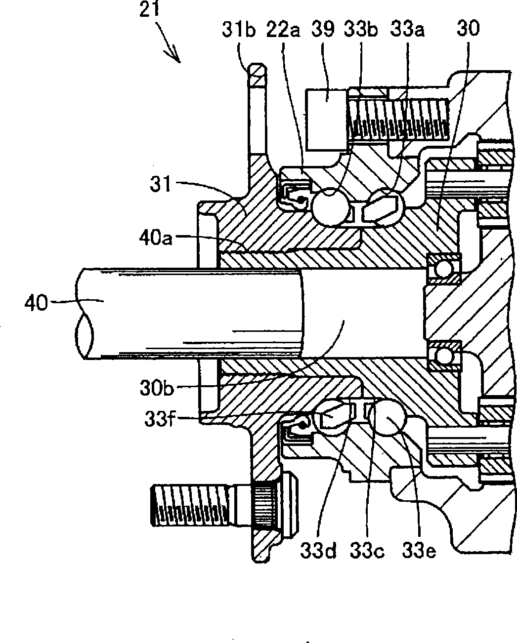
An in-wheel motor drive unit (21) comprising a casing (22), a motor unit (A), a decelerating unit (B), a wheel hub (31), and a wheel hub bearing (33) for rotataly supporting the wheel hub (31) on the casing (22). The wheel hub bearing (33) includes first and second outside raceway surfaces (33a, 33b) provided on the inner diameter surface of the casing (22), a first inside raceway surface (33c) provided on the outer diameter surface of a wheel-side rotating member (30) to face the first outside raceway surface (33a), a second inside raceway surface (33d) provided on the outer diameter surface of the wheel hub (31) to face the second outside raceway surface (33b), and a plurality of rolling elements (33e) disposed between the outside raceway surfaces (33a, 33b) and the inside raceway surfaces (33c, 33d).

Description

technical field [0001] The invention relates to an in-wheel motor driving device which independently rotates and drives each driving wheel. [0002] In addition, the present invention relates to an in-wheel motor drive device in which an output shaft of a motor and a hub of a wheel are coaxially connected via a speed reducer. Background technique [0003] A conventional in-wheel motor driving device is described in, for example, Japanese Unexamined Patent Publication No. 2001-32914. The in-wheel motor drive device described in this publication includes a motor that generates a drive wheel, a speed reducer that decelerates the rotation of the motor and transmits it to the drive wheel, and a hub that rotatably holds the drive wheel. [0004] A planetary gear mechanism including a sun gear provided on an input shaft, an internal gear fixed to a casing, and a planetary gear arranged between the sun gear and the internal gear and connected to an output shaft is used as the speed...

Claims


Application Information

Patent Timeline
Patent Type & Authority Applications(China)
IPC IPC(8): F16H1/32F16C33/64B60K7/00F16C35/063F16C19/18F16H1/36
CPCY02T10/641
Inventor 铃木稔
Owner NTN CORP
Why Eureka
Try Eureka