Diagnosis device of chain slack for passenger conveying equipment and diagnosis method

A technology for passenger conveying equipment, diagnostic devices, applications in transport and packaging, energy efficiency of escalators, climate sustainability, etc.

Active Publication Date: 2009-04-01
HITACHI LTD +1
View PDF1 Cites 21 Cited by
  • Summary
  • Abstract
  • Description
  • Claims
  • Application Information

AI Technical Summary

Problems solved by technology

However, even if the output torque is suppressed to such a magnitude that the main drive sprocket does not rotate through motor control, it is technically difficult to maintain the main drive sprocket in a state where the main drive sprocket does not rotate due to the

Method used


Image

  • Diagnosis device of chain slack for passenger conveying equipment and diagnosis method
  • Diagnosis device of chain slack for passenger conveying equipment and diagnosis method
  • Diagnosis device of chain slack for passenger conveying equipment and diagnosis method

Examples


no. 1 approach

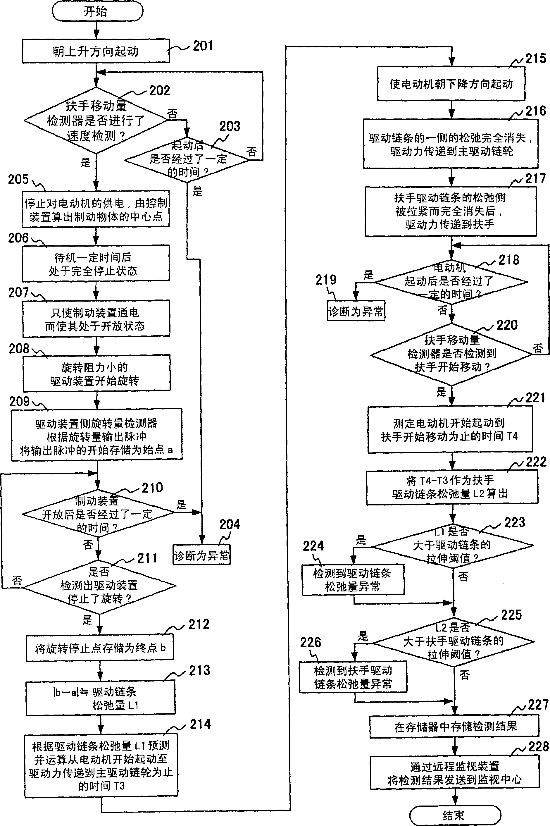
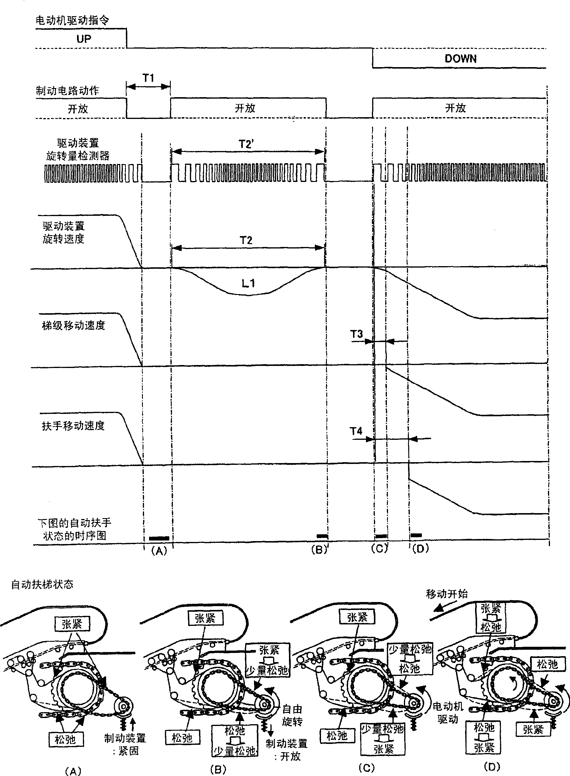
[0054] refer to figure 2 as well as image 3 The operation of the first embodiment will be described. figure 2 It is a flowchart of the slack amount diagnosis operation of the drive chain and the handrail drive chain in the escalator with the descending direction as the normal running direction. image 3 is to carry out figure 2 An operation explanatory diagram and a timing chart of the operation of each part at the time of the slack amount diagnosis are shown.

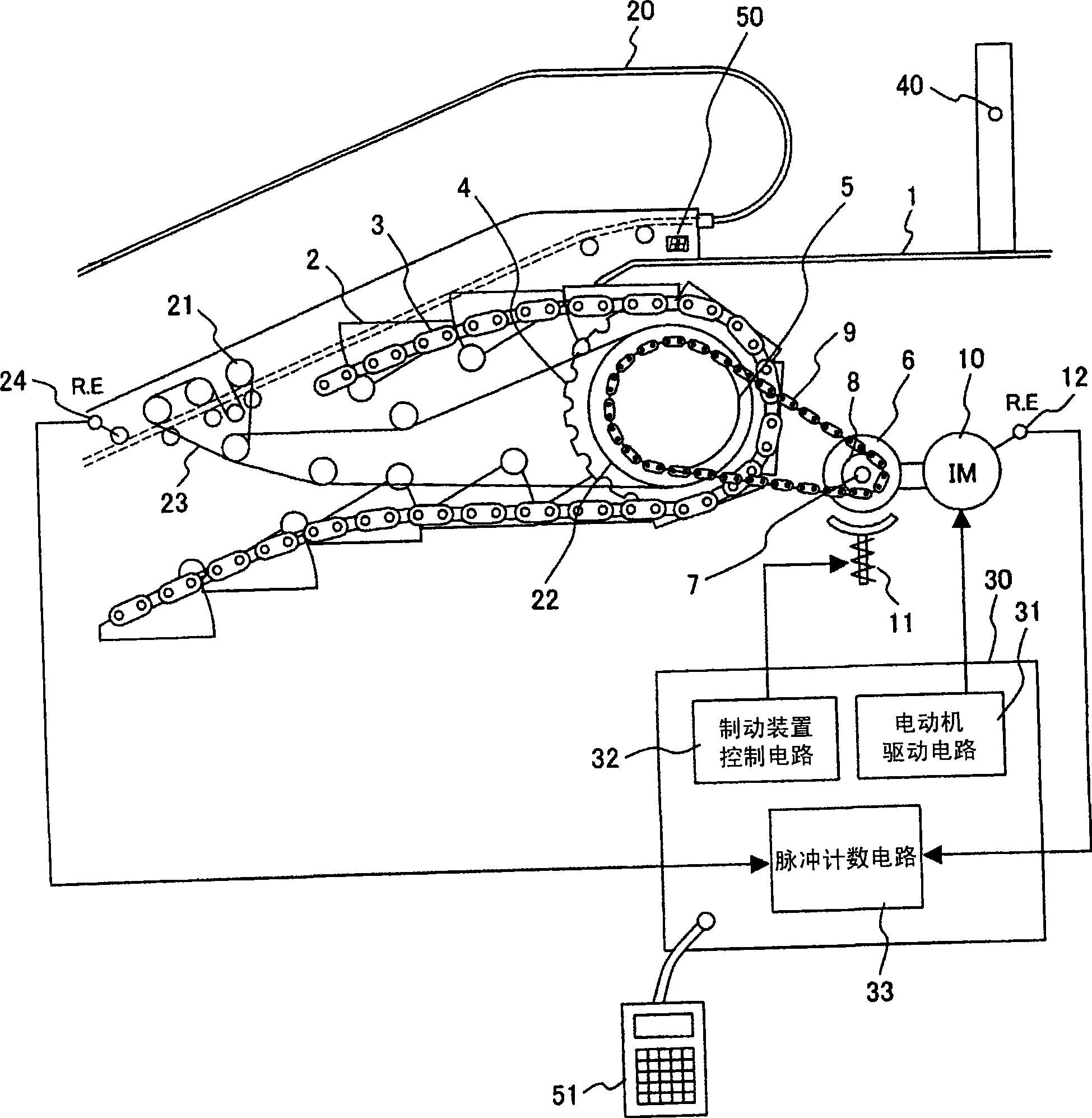
[0055]After receiving a diagnostic command for chain slack not shown in the figure, the escalator 1 is started in the upward direction by step 201, and then the driving force is transmitted to the handrail 20 in step 202, and is monitored by the handrail movement amount detector 24. Whether the movement of the escalator has started. When some abnormality occurs in the equipment of the escalator, and after a certain period of time, the driving force is still not transmitted to the handrail 20, thus causing the h...

no. 2 approach

[0067] Refer to the following Figure 4 The shown flow chart explains the second embodiment. This second embodiment is performed as figure 1 As shown, on the front side of the escalator entrance, a sensor 40 for detecting passengers getting in is provided, and when the sensor detects that a passenger is getting in, the escalator is started to carry out the second embodiment of the so-called automatic operation.

[0068] As described in the first embodiment, when the escalator is stopped because there are no passengers, the slack diagnosis of the drive chain 9 and the handrail drive chain 23 is performed. For this reason, in step 401, the passenger detection sensor 40 that is arranged on the front side of the escalator entrance and exit detects that the escalator is in the state of no passenger, and confirms that the escalator is in the standby state. Thereafter, in step 402, calculate according to the time information stored in the escalator control device 30 and the running...

no. 3 approach

[0071] Refer to the following Figure 5 The shown flow chart explains the third embodiment. The third embodiment is as figure 1 Shown is a third embodiment in which diagnosis is performed during maintenance work in an escalator provided with a status display 50 for displaying the status of the escalator and in which a maintenance portable terminal 51 is connectable to the escalator control device 30 .

[0072] In step 501, it is detected whether the escalator is in the state of maintenance work, and if it is not in the state of maintenance work, no diagnosis is performed. In step 502, in the maintenance work, after performing a specific password operation which is not used in general maintenance work, it proceeds to the slack amount diagnosis step 504 of the drive chain 9 and the handrail drive chain 23 . As a specific password operation, for example, a method such as continuously pressing the stop switch for 5 seconds, and then pressing the stop switch 5 times within 10 sec...


PUM


Abstract

A driving chain of a passenger conveyor and/or the relaxation amount of armrest driving chain are diagnosed at a condition that an accurate motor control technique and a special stair moving sensor are not required. The passenger conveyor (1) is moved to a direction through a motor (10) and then is braked for stopping. A braking device is activated at a state that the power supply to the motor (10) is cut off. The rotation amount of a driving shaft (7) is detected through a rotation amount detector (12). The relaxation amount of a driving chain (9) is calculated based on the rotation amount. Furthermore the motor is driven to rotate along a reverse direction, the total delay time (T4) to a time when the moving of armrest (20) is detected through an armrest moving amount detector (24). The relaxation amount (L2) of the armrest driving chain (23) is calculated through subtracting a calculated value (L1) corresponding with the relaxation amount of the driving chain (9) from the total delay time.

Description

technical field [0001] The present invention relates to a slack diagnostic device and diagnostic method for a driving chain and / or a handrail driving chain of passenger conveying equipment such as an escalator and an electric walkway. Background technique [0002] Patent Documents 1 and 2 and the like are known as techniques for measuring slack in drive chains of passenger conveyors. [0003] First, in Patent Document 1, the driving force of the motor of the driving device is reduced to a driving force lower than the driving force required to rotate the main driving sprocket, and the main driving sprocket is driven by the above-mentioned reduced driving force. Turn in one direction so that one side of the drive chain is tensioned, starting from the rotational position of the drive at this point. Thereafter, the motor is rotated in the other direction, so that the other side of the drive chain is tensioned, and the rotation position of the drive device at this time is taken ...

Claims


Application Information

Patent Timeline
IPC IPC(8): B66B29/00B66B25/00B66B23/02
CPCY02B50/22Y02B50/225
Inventor 坂上充一濑卓也五十岚芳治盐山纯
Owner HITACHI LTD
Why Eureka
Try Eureka