
Method for eliminating channel delay errors based on TDOA (time difference of arrival) positioning

A delay error and delay difference technology, applied in the field of channel delay error elimination based on TDOA positioning, can solve problems such as channel delay difference, affecting positioning accuracy, and air transmission distance difference, so as to improve accuracy and avoid interference Effect

Inactive Publication Date: 2011-09-21
XIDIAN UNIV
View PDF3 Cites 23 Cited by
  • Summary
  • Abstract
  • Description
  • Claims
  • Application Information

AI Technical Summary

Problems solved by technology

[0005] In the actual network positioning, due to the unavoidable differences between the analog channels of different monitoring nodes, the time delays formed when the monitored signals pass through different channels are different, so that the time delay difference estimated by the above algorithm not only includes the signal in the air The propagation time delay difference also includes the channel delay difference, which makes the distance difference calculated from the time delay difference have a large error
For example, in the article "Time-Delay Estimation via Linear Interpolation and Cross Correlation" published by Jaccob Benesty et al. in IEEE in September 2004, only using the TDOA value calculated by the correlation method including the actual channel delay error for positioning will cause large error
It can be seen that during network positioning, if the channel delay difference cannot be eliminated, the air transmission distance difference cannot be accurately calculated, thereby affecting the positioning accuracy

Method used


Image

  • Method for eliminating channel delay errors based on TDOA (time difference of arrival) positioning
  • Method for eliminating channel delay errors based on TDOA (time difference of arrival) positioning
  • Method for eliminating channel delay errors based on TDOA (time difference of arrival) positioning

Examples


Embodiment Construction

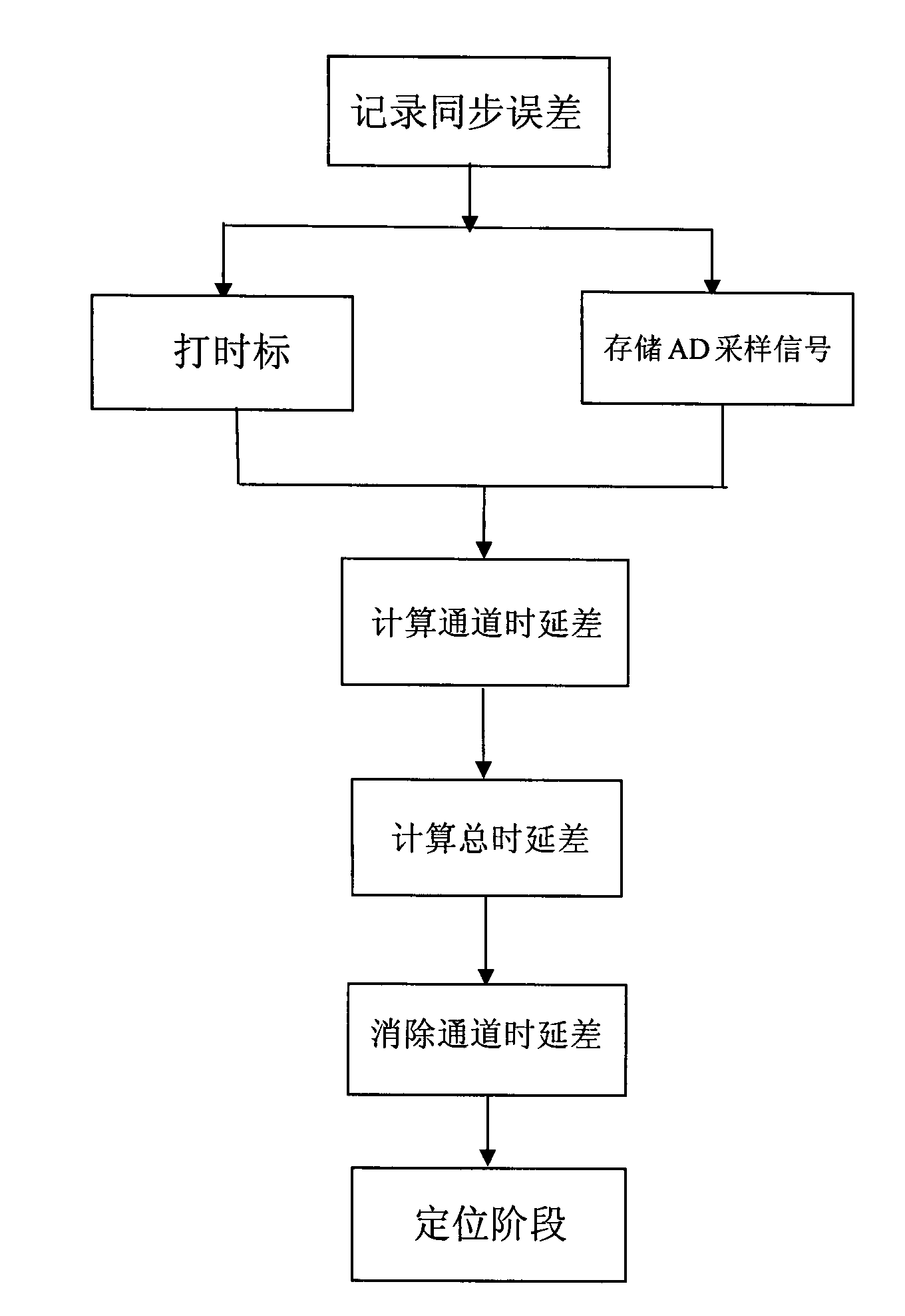
[0021] refer to figure 1 , the implementation steps of the present invention are as follows:

[0022] Step 1, record the synchronization error

[0023] Read the time recorded respectively from n GPS instruments installed on n monitoring nodes, and record the time synchronization error between n monitoring nodes, respectively δ i,j , i, j=1, 2, 3, . . . , n, and i≠j, it is determined that the error is within the allowable range, and accurate time synchronization between n monitoring nodes is realized.

[0024] Step 2, process the detected signal

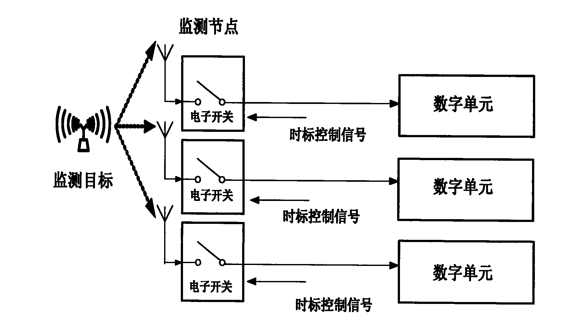
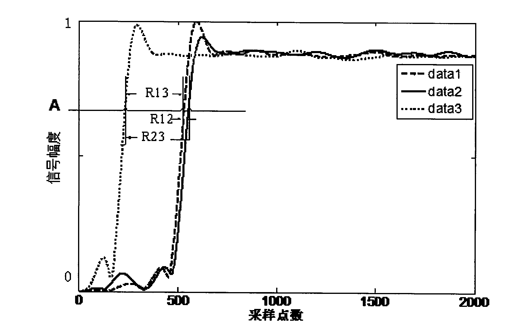
[0025] 2a) Reference figure 2 , after receiving the positioning command, the digital units of n monitoring nodes send the channel opening control signal to the electronic switch at the channel entrance of the monitoring node at the same time, and the electronic switch opens the channel at the same time after receiving the unified channel opening control signal, forming a The rising edge of the signal, the time difference between ...


PUM


Abstract

The invention discloses a method for eliminating channel delay errors based on TDOA (time difference of arrival) positioning, which solves the problem of large positioning-result errors caused by the interference (arising from the channel delay difference of a monitoring node) on the TDOA measurement value. The method comprises the following steps that: a clock synchronizer GPS (global position system) carries out clock synchronization on a receiver; after receiving a positioning instruction of a positioning network management center, the receiver carries out time mark making on monitored signals at the same moment; simultaneously, a monitoring-node digital unit stores AD (alternating / direct) sampling signals; a monitoring node sends the AD sampling signals to the management center, and the management center carries out statistics on the channel delay difference of the receiver; the management center calculates the total delay difference according to a GCC (Gnu C Compiler) algorithm; the management center calculates an air transmission delay difference by using the total delay difference and the channel delay difference; and the management center positions target nodes according to the air transmission delay difference. By using the method disclosed by the invention, the errors (arising from the channel delay difference) on time delay estimation can be reduced, and the accuracy of network positioning can be improved.

Description

technical field [0001] The invention belongs to the field of communication technology, and further relates to the field of wireless communication technology and signal processing technology, in particular to a method for eliminating channel delay errors based on Time Difference of Arrival (TDOA) positioning, which can be used in cellular networks and wireless sensors When TDOA positioning is used in the electromagnetic spectrum signal source positioning and tracking business of the network or other networks, channel delay errors between monitoring devices are eliminated. Background technique [0002] With the rapid development of mobile communication technology, electromagnetic spectrum signal source location technology has become a must-have function for the next generation mobile communication system. In recent years, research results have shown that because the electromagnetic spectrum monitoring work is mostly passive monitoring of signals, the control of the monitored t...

Claims


Application Information

Patent Timeline
IPC IPC(8): H04W64/00H04B17/00
Inventor 李赞郝本建刘海波赵翌远齐佩汉关磊司江勃高锐
Owner XIDIAN UNIV
Learn More