
Vacuum electromagnetic regulator

A regulator and vacuum technology, applied in the direction of machines/engines, adding non-fuel substances to fuel, internal combustion piston engines, etc.

Inactive Publication Date: 2010-08-04
WUXI LONGSHENG TECH
View PDF3 Cites 0 Cited by
  • Summary
  • Abstract
  • Description
  • Claims
  • Application Information

AI Technical Summary

Problems solved by technology

[0003] The invention aims at the problems in the existing vacuum electromagnetic regulator, and provides a vacuum electromagnetic regulator which is not easy to enter dust and produces less noise

Method used


Image

  • Vacuum electromagnetic regulator
  • Vacuum electromagnetic regulator
  • Vacuum electromagnetic regulator

Examples


Embodiment Construction

[0016] The present invention will be further described below in conjunction with drawings and embodiments.

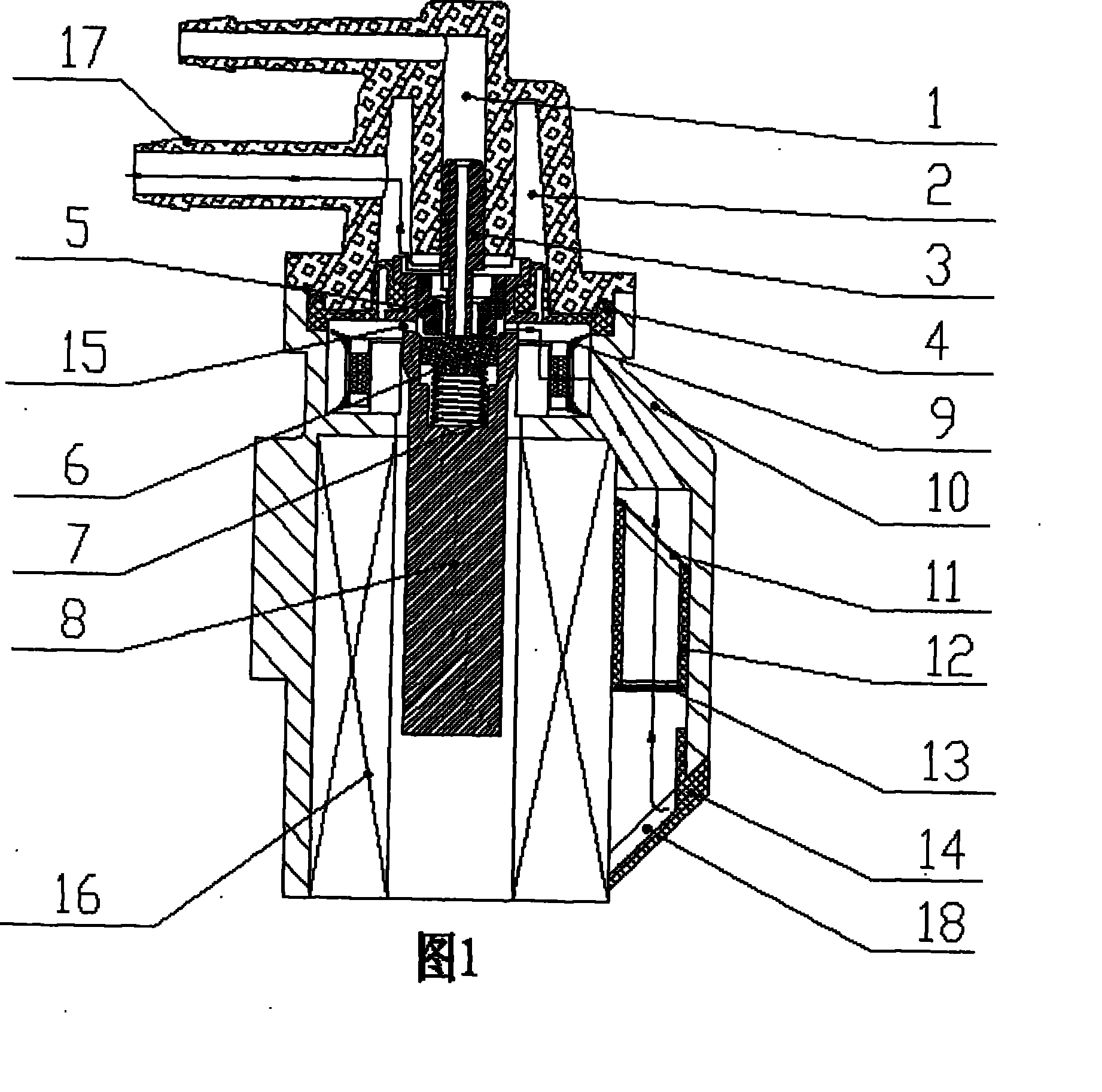
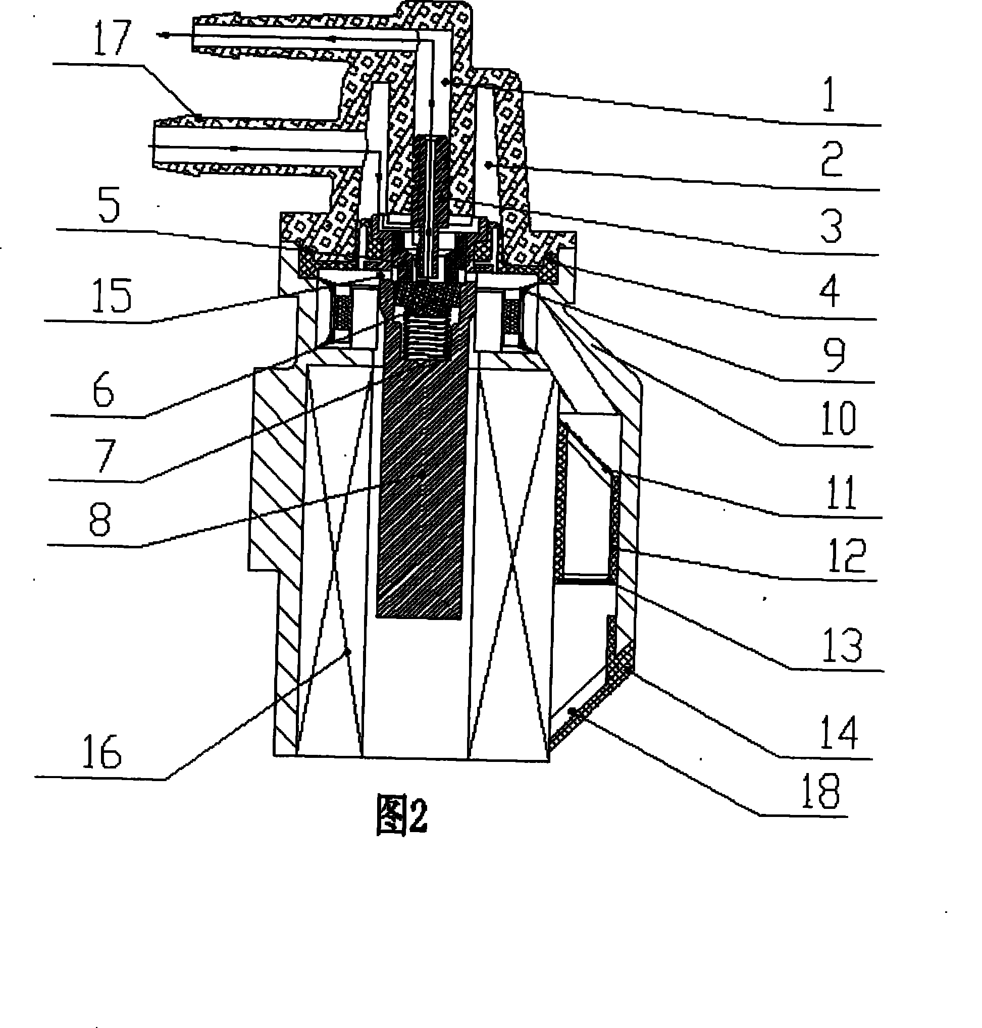
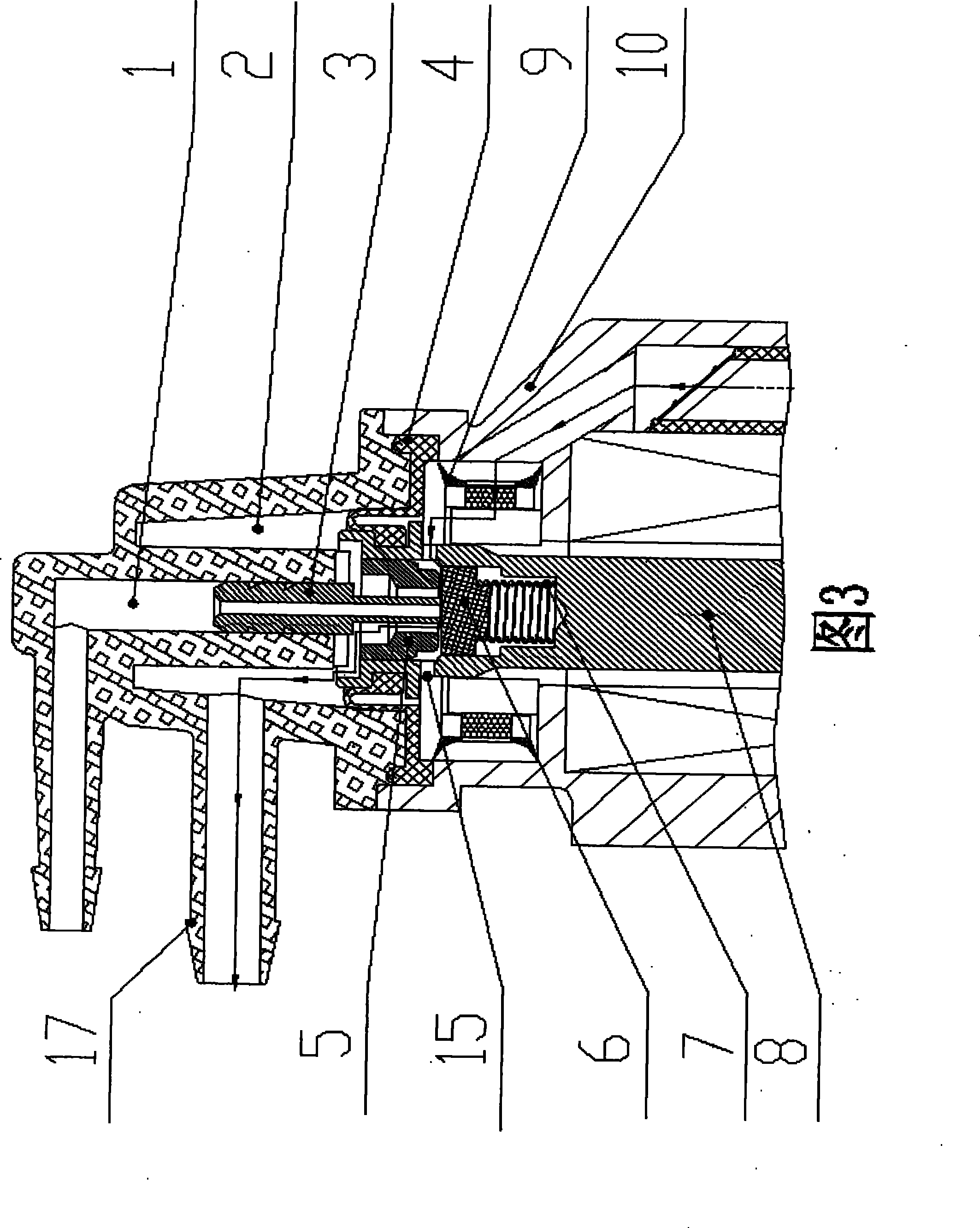
[0017] A vacuum electromagnetic regulator, comprising a valve body 10, a valve cover 17 connected to the upper part of the valve body 10, a valve core 8 in the valve body 10, an air channel 18 is arranged on one side of the valve body 10, and an air channel 18 is arranged in the air channel 18 Air filter membrane, spring 7 is set in the inner cavity of the upper part of the valve core 8, the upper part of the spring 7 is covered with an on-off film 6, the upper part of the on-off film 6 is provided with a stopper 5, and there is a hole in the middle of the stopper 5, and the on-off film 6 and the stopper The outer ring of 5 is matched with the upper inner cavity of the valve core 8, the valve cover 17 is provided with a vacuum input chamber 1 and a vacuum output chamber 2, and a thimble 3 is arranged in the vacuum input chamber 1, and the lower part of the thimble 3 pass...


PUM


Abstract

The invention discloses a valve opening regulation device in a tail gas exhaust and exhaust gas recirculation system of an engine, namely a vacuum electromagnetic regulator. The technical proposal is that the vacuum electromagnetic regulator comprises a valve body, a valve cover which is connected with the upper part of the valve body and a valve core in the valve body. One side in the valve bodyis provided with an air path in which an air filter membrane is arranged. An internal cavity at the upper part of the valve core is provided with a spring and the upper part of the spring is sheathedwith a switching leather diaphragm while the upper part of the switching leather diaphragm is provided with a baffle block provided with holes in the middle. The switching leather diaphragm and an outer ring of the baffle block match with the internal cavity at the upper part of the valve core. The valve cover is internally provided with a vacuum input cavity and a vacuum output cavity while the vacuum input cavity is internally provided with an ejector pin. The lower part of the ejector pin passes through the hole in the middle of the baffle block to support against the end face of the switching leather diaphragm. The middle of the ejector pin is provided with a through hole which is communicated with the vacuum input cavity. A sealing feather diaphragm is arranged between the valve bodyand the valve cover. Air intake from the bottom of an inlet channel is changed to a mode that air intake from side face of the vacuum electromagnetic regulator, and then air enters an air inlet at the upper part of the valve core of the regulator so as to avoid air-stream noise caused when air enters from the bottom of the valve core of the vacuum electromagnetic regulator. The amount of the air filter membrane is added into three layers and the step-by-step filtering method is adopted to effectively prevent dust from entering the interior of the vacuum electromagnetic regulator.

Description

technical field [0001] The invention relates to a valve opening adjustment device in an engine tail gas exhaust gas recirculation system (EGR), belonging to an engine tail gas emission control device. Background technique [0002] The vacuum electromagnetic regulator is an adjusting device that regulates the recirculation exhaust gas flow in the engine exhaust gas recirculation system (EGR system), and plays an important role in the entire system. Its main function is to change the current of the vacuum electromagnetic regulator coil to Change the magnitude of the magnetic field force to push the valve core to move inside the valve, and then adjust the on-off gap and frequency between the vacuum input and the atmosphere in the needle valve to achieve the purpose of adjusting the output of different vacuum degrees. Since the spool of the electromagnetic regulator needs to maintain a uniform magnetic field gap when it moves inside the valve body, the gap between the spool and ...

Claims


Application Information

Patent Timeline
Patent Type & Authority Patents(China)
IPC IPC(8): F02M25/07F02M26/57
CPCY02T10/121Y02T10/12
Inventor 邓树平彭俊曾劲平徐伟孙骋业
Owner WUXI LONGSHENG TECH
Learn More