Supercharge Your Innovation With Domain-Expert AI Agents!

Rotor type compressor

A compressor and rotor type technology, applied in the field of compressors, can solve the problems of increasing the dynamic balance of the compressor, difficult to remove the inertial force, increasing the friction and wear of the compressor, etc., and achieves the effect of reducing friction and wear and achieving good balance.

Inactive Publication Date: 2009-04-01
陈君立 +1
View PDF0 Cites 0 Cited by
  • Summary
  • Abstract
  • Description
  • Claims
  • Application Information

AI Technical Summary

Problems solved by technology

The advantage of the above-mentioned oscillating rotor compressor is that the structure is simple and reliable, especially the inner and outer ends of the blades are supported, unlike some vane compressors that only have a single head support and the blades are cantilevered, so the blades are in better stress condition At the same time, the friction and leakage between the blade and the rotor are also less; however, the traditional swing rotor compressor also has obvious defects, such as the rotor adopts the swing motion working mode, on the one hand, it is difficult to remove the inertial force of the swing motion, which increases On the other hand, due to the large rotation radius of the rotor, there is a relatively large relative motion speed between the rotor and the cylinder, the rotor and the end cover, which increases the friction and wear of the compressor.

Method used


Image

  • Rotor type compressor
  • Rotor type compressor
  • Rotor type compressor

Examples


Embodiment Construction

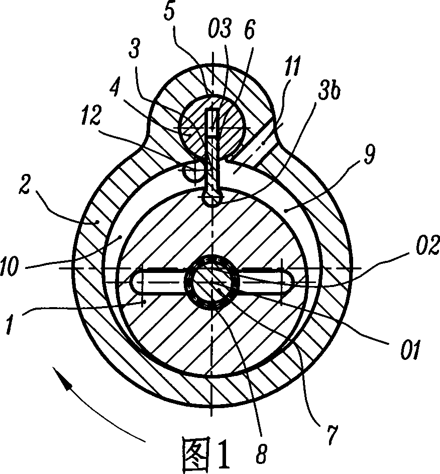
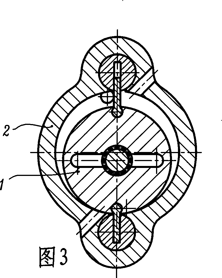
[0009] Fig. 1 and Fig. 2 show a cross-sectional schematic diagram and a working state diagram of an embodiment of a rotary compressor of the present invention. In this embodiment, the rotary compressor includes a rotor 1, a cylinder 2, a blade 3, a rotating column 4, and two end covers (not shown in the figure); the rotor 1 has a cylindrical The outer surface, the cylinder 2 has a circular hole-shaped inner hole surface, the inner end of the blade 3 is made into a cylindrical head shape, and the rest is flat, and the rotating column 4 has a cylindrical outer surface; the rotor 1 is offset In the cylinder 2, the rotor axis O1 and the cylinder axis O2 are arranged in parallel, the distance between the two axes is the eccentricity of the rotor 1 relative to the cylinder 2, and the outer surface of the rotor 1 is tangentially matched with the inner surface of the cylinder 2 (movement clearance is allowed or oil film gap); a cylindrical hole 3b parallel to the rotor axis O1 is open...


PUM


Abstract

The invention discloses a rotor compressor which comprises a rotor (1), a cylinder (2), a vane (3), a rotating column (4) and an end cover; the rotor (1) has a cylindrical outer surface; the cylinder (2) has a circular-hole inner hole-surface; the rotating column (4) has a cylindrical outer surface; the rotor (1) is biased in the cylinder (2); the outer surface of the rotor (1) is tangent and in contact with and is matched with the inner hole-surface of the cylinder (2). The a rotor compressor is characterized in that the rotor (1) conducts translation and rotation under the restrict of a translation mechanism; a cylinder hole (3b) is cut on the rotor (1); the inner end of the vane (3) is made into a cylindrical head and is articulated and matched with the cylinder hole (3b); a circular-arc groove (5) is cut on the cylinder (2); the rotating column (4) is arranged in the circular-arc groove (5) and rotates and is matched with the circular-arc groove (5); a compressed sliding groove (6) is cut on the rotating column (4); the vane (3) is inserted into the sliding groove (6) and slides and is matched with the sliding groove (6); as the rotor (1) conducts translation and rotation, the movement velocity of the rotor (1) to the cylinder (2) and the end cover is quite small, which is beneficial to reducing friction and abrasion; besides, the balance of the rotor compressor is good.

Description

technical field [0001] The invention relates to a compressor, in particular to a rotary compressor. Background technique [0002] Among all kinds of compressors, there is a swing rotor compressor which is very distinctive. This compressor has a rotor, a cylinder, a vane, a rotating column and two end covers; the rotor has a cylindrical outer surface, The cylinder has a circular hole-shaped inner surface, the blades are flat, and the rotating column has a cylindrical outer surface; the rotor is offset in the cylinder, and the axis of the rotor is parallel to the axis of the cylinder, and the two axes The distance is the so-called eccentricity. The axis of the rotor rotates around the axis of the cylinder, and the outer surface of the rotor is in tangential contact with the inner surface of the cylinder; along the axis parallel to the cylinder, a cylindrical rotating column hole is opened on the cylinder. , the rotating column is fitted in the rotating column hole and rotates...

Claims


Application Information

Patent Timeline
IPC IPC(8): F04C18/44F04C23/00F04C29/00
Inventor 陈君立李辛沫耿爱农阮勤江
Owner 陈君立
Features
  • R&D
  • Intellectual Property
  • Life Sciences
  • Materials
  • Tech Scout
  • Unparalleled Data Quality
  • Higher Quality Content
  • 60% Fewer Hallucinations
Learn More