Self-adapting steering headlamp illuminating system

A lighting system and self-adaptive technology, which is applied in adaptive control, lighting devices, general control systems, etc., can solve the problems that the headlight irradiation direction is too high, the headlight angle cannot be calculated, and the headlight irradiation direction is low. Achieve the effects of improving portability, reducing implementation costs, and reducing maintenance costs

Inactive Publication Date: 2009-04-01
杰克陈
View PDF0 Cites 12 Cited by
  • Summary
  • Abstract
  • Description
  • Claims
  • Application Information

AI Technical Summary

Problems solved by technology

However, this type of AFS system still has the following problems, for example, as Figure 5a As shown, when the vehicle moves along the slope of θ W When the slope is going uphill, the acceleration sensor here can only calculate the angle θ between the direction of headlight irradiation (indicated by a solid line in the figure) and the direction of illumination before going uphill (indicated by a dotted line in the figure). L , but it is impossible to calculate the angle between the direction of the headlight irradiation and the actual direction of the line connecting the front and rear axles
In addition, those skilled in the art should be able to deduce that since the vehicle goes uphill, the head of the vehicle will be tilted up, so θ L >θ W , so if the angle that the headlight should rotate in the up and down direction calculated by the ECU is larger than the angle that it should rotate, so that the adjusted headlight's irradiation direction is actually too low, so its control Unsatisfactory effect
Similarly, if Figure 5b As shown, when the vehicle moves along the slope θ W When the slope is downhill, the downhill will cause the front of the car to deflect downward, so θ L >θ W , so the angle that the headlight should rotate in the up and down direction calculated by the ECU is larger than the angle that it should rotate, so that the adjusted headlight's irradiation direction is actually too high, so its control effect is not good. ideal

Method used


Image

  • Self-adapting steering headlamp illuminating system
  • Self-adapting steering headlamp illuminating system
  • Self-adapting steering headlamp illuminating system

Examples


Embodiment Construction

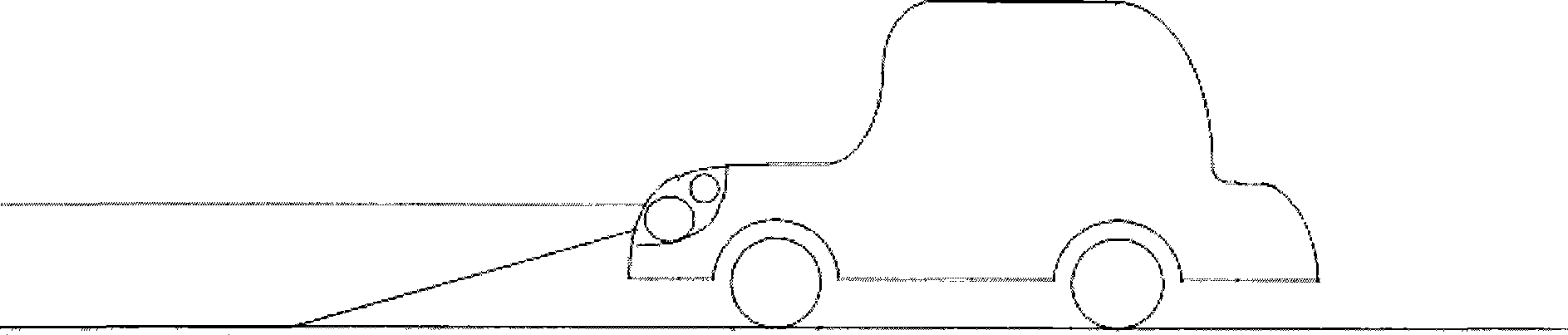
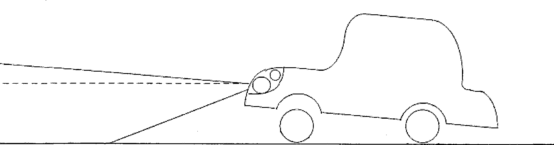
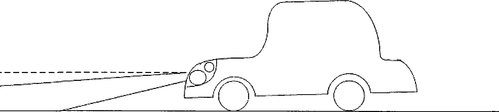
[0023] Such as Image 6Shown is a schematic structural diagram of the adaptive steering headlight lighting system of the present invention, including: a first acceleration sensor 62 installed at the front wheel of the vehicle. In one embodiment, the first acceleration sensor 62 is a 2D acceleration sensor, which can be used to measure at least: (1) the acceleration change of the vehicle in the direction of gravitational acceleration; Acceleration change in direction. The angle change of the vehicle in the up and down direction can be calculated through the acceleration changes in the (1) and (2) directions. In another embodiment, the first acceleration sensor 62 can also be a 3D acceleration sensor, which can also be used to measure the acceleration change of the vehicle in two directions perpendicular to the above-mentioned (1) and (2) at the same time, by The acceleration change and the acceleration change in the (2) direction can calculate the angle change of the vehicle ...


PUM


Abstract

The invention discloses an adaptive front turn lamp lighting system. A 2D or 3D acceleration transducer is respectively installed on the lamp and the rotor shafts of the front wheels of a car to measure the angle changes of the car and the front lamp in up, down, right and left directions, and then the turning angles of the front lamp in up, down, right and left directions are calculated through ECU integration, and the turning of the front lamp is controlled by a lamp turning drive and control module, thereby guaranteeing that the illumination of the front lamp in up, down, right and left directions can be correctly adjusted whether the car is in an upslope state or downslope state, accelerates or decelerates, or drives on an uneven road or makes a turn, so that the driving safety of the car is enhanced; the invention also reduces the complexity of the structure of an AFS system and realization cost and improves the transportability of the components in the system; besides, the system also reduces the possible maintenance cost of users and increases the possibility of being popularized for use.

Description

technical field [0001] The invention relates to an adaptive front-lighting system (AFS, Adaptive Front-Lighting System), in particular to an adaptive front-lighting system which uses an acceleration sensor to measure changes in vehicle posture and left-right steering angles. Background technique [0002] In order to ensure the driving safety of the vehicle, it should generally be ensured that the irradiation direction of the vehicle light is parallel to the connection line between the front and rear wheel axles of the vehicle, specifically as follows: figure 1 shown. However, the commonly used vehicle headlights generally cannot adjust their lighting modes according to specific conditions such as changes in vehicle posture and vehicle turning. In actual situations, for example, when passengers get on or off the car, loading or unloading, the load of the vehicle will change, which will cause the front of the vehicle to tilt up or down; When the slope or the road is uneven, ...

Claims


Application Information

Patent Timeline
Patent Type & Authority Applications(China)
IPC IPC(8): F21S8/10H05B37/02B60Q1/076G05B13/02F21W101/10
Inventor 杰克陈
Owner 杰克陈
Why Eureka
Try Eureka