Indicating lamp structure

A technology of indicator lamps and casings, which is applied in the direction of damage prevention measures for lighting devices, lighting applications, lighting and heating equipment, etc. It can solve problems such as misjudging the use status of electronic products and affecting the aesthetics of electronic products, so as to prevent light leakage Effect

Inactive Publication Date: 2009-04-01
HONG FU JIN PRECISION IND (SHENZHEN) CO LTD +1
View PDF0 Cites 13 Cited by
  • Summary
  • Abstract
  • Description
  • Claims
  • Application Information

AI Technical Summary

Problems solved by technology

However, during the use of electronic products, consumers often encounter the phenomenon that some adjacent indicator lights will interfere, that is, when one indicator light is shining, the adjacent indicator lights are also flickering, so that It will make consumers misjudge the use status of electronic products, and at the same time affect the aesthetics of electronic products

Method used


Image

  • Indicating lamp structure
  • Indicating lamp structure

Examples


Embodiment Construction

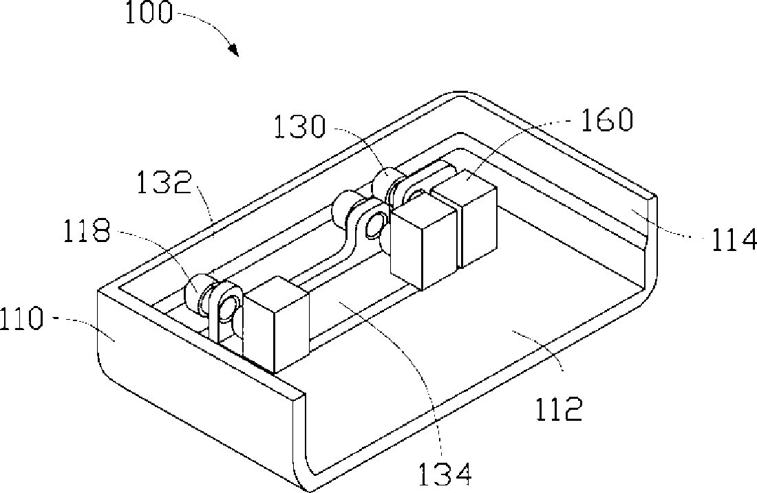
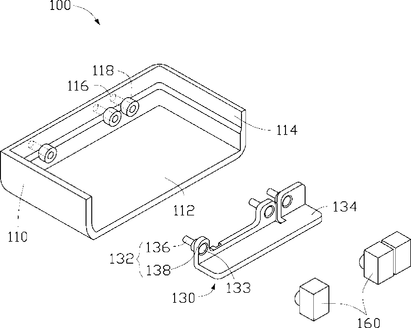
[0008] Please also refer to figure 1 and figure 2 , a preferred embodiment of the indicator light structure of the present invention, the indicator light structure 100 includes an electronic product casing 110 (hereinafter referred to as the casing 110 ), a light guide assembly 130 and a group of light sources 160 .

[0009] The casing 110 includes a bottom plate 112 and a side wall 114 surrounding the bottom plate 112 and forming a certain angle with the bottom plate 112 . The bottom plate 112 and the side wall 114 form a casing. In this embodiment, the sidewall 114 is substantially perpendicular to the bottom plate 112 . A plurality of light outlet holes 116 are formed on the side wall 114 , and the light outlet holes 116 are used to allow the light emitted by the light source inside the electronic product to pass through. A shading element 118 extends toward the inside of the casing 110 along the edge side wall 114 of the light exit hole 116 , and the shading element 118...


PUM


Abstract

The invention provides a structure of a pilot lamp. The structure of the pilot lamp comprises a shell, a light guiding component and a light source, wherein, the shell comprises a bottom plate and side walls enclosing the bottom plate and a plurality of light outlet holes are arranged on the side walls; the light guiding component comprises a plurality of light guiding columns arranged between the light source and the light outlet holes of the shell and is used for transmitting the light emitted by the light source to the light outlet holes of the shell; the light source comprises a plurality of light emitting parts which are respectively corresponding to the light guiding columns, and is arranged in the shell corresponding to the light guiding columns and electrically connected with a control circuit. As to the light guiding columns which are adjacent to each other, at least one light guiding column is wrapped with a shading element in the side wall and one end of each light guiding column stretches into the light outlet hole of the shell. Additionally, the structure of the pilot lamp can prevent light leak.

Description

technical field [0001] The invention relates to an indicator light structure, in particular to an indicator light structure applied to consumer electronic products. Background technique [0002] With the development of society, continuous advancement of science and technology, and the continuous improvement of people's living standards, consumer electronics products have become the new favorites that people are constantly chasing. Consumer electronics have become more abundant than ever. When a wide range of electronic products are flooding people's eyes, fashionable, beautiful and refined electronic products are more popular with consumers. Various indicator lights installed inside electronic products have also become a highlight of electronic products. Various indicator lights not only have the function of indicating various states of products, but also increase the ornamental value of electronic products, thus becoming An indispensable part of electronic products. Howev...

Claims


Application Information

Patent Timeline
Patent Type & Authority Applications(China)
IPC IPC(8): F21V8/00F21V15/02F21W111/00F21Y101/02
CPCF21V11/00F21V15/01F21W2111/00F21S8/00
Inventor 邬进义
Owner HONG FU JIN PRECISION IND (SHENZHEN) CO LTD
Why Eureka
Try Eureka