Forced centering plate and embedding method

A technology of centering plate and centering plate, which is applied in the field of measurement to achieve the effects of long service life, enhanced stability, and anti-tilt

Inactive Publication Date: 2009-04-01
WUHAN SURVEYING GEOTECHN RES INST OF MCC
View PDF0 Cites 9 Cited by
  • Summary
  • Abstract
  • Description
  • Claims
  • Application Information

AI Technical Summary

Problems solved by technology

[0002] In high-precision engineering measurement, the centering error of the instrument and the target is required to be less than 0.2mm, which cannot be met by the conventional optical projection method and vertical ball alignment method

Method used


Image

  • Forced centering plate and embedding method
  • Forced centering plate and embedding method
  • Forced centering plate and embedding method

Examples


Embodiment 1

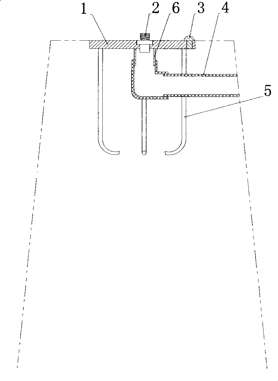
[0021] According to Figure 1, figure 2 As shown, a forced centering plate includes: a centering plate 1, a connecting bolt 2 is installed in the center hole of the centering plate 1, a leveling point 3 is also installed on the centering plate 1, and a connecting pipe is installed at the bottom of the centering hole of the centering plate 1 6. The PVC pipe 4 (rainwater diversion hole) connected to the connecting pipe 6, and at least two fixed steel bars 5 are also arranged on the bottom surface of the centering plate 1 .

[0022] The machining error of the center hole diameter of the centering plate 1 should not be greater than +0.1mm, and the diameter machining error of the connecting bolt 2 and the center hole should not be greater than -0.1mm.

[0023] Centering plate 1, connecting bolt 2 and leveling point 3 should be made of stainless steel.

Embodiment 2

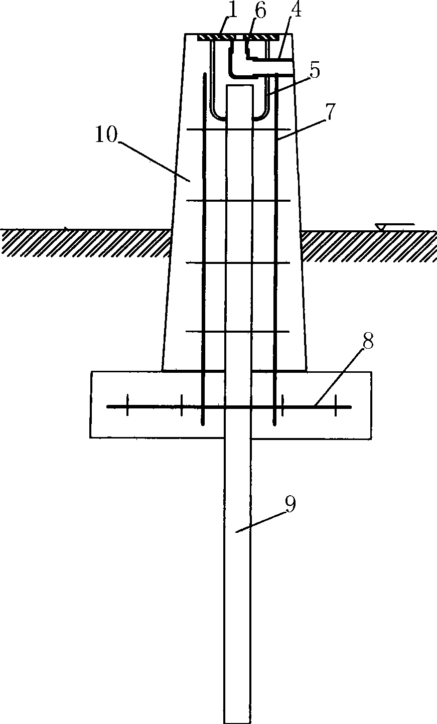
[0025] according to image 3 As shown, a method of embedding forced centering panels, the steps are as follows:

[0026] ① Excavate a square pit with a side length of 1-1.5m and a depth of 1.3-1.5m;

[0027] ②Drill a steel pipe 9 with a diameter of 400-600mm into the center of the pit, and its depth is 3-5m above the ground;

[0028] ③ Placing a 1-1.2m square reinforced chassis circle 8 under the horizontal plane 1-1.2m;

[0029] ④ Tie a square cylindrical reinforcement ring 7 with a height of 1.8-2.2m on the chassis reinforcement ring 8, and its side length is 250mm;

[0030] 5. Weld the fixed steel bar 5 of the forced centering plate on the steel pipe 9 top, the upper surface of the centering plate 1 of the forced centering plate must be kept in a horizontal state, and formwork is installed outside the reinforcement circle 7, 8;

[0031] ⑥Pour concrete so that the surface of the forced centering plate is flush with the horizontal plane of the centering observation pier 10...


PUM


Abstract

The invention provides a forcing centering plate, comprising a centering plate (1). A central hole of the centering plate (1) is provided with a connecting bolt (2); the centering plate (1) is also provided with a bench mark (3); the bottom of the central hole of the centering plate (1) is provided with a connecting pipe (6) and a PVC pipe (4) which is connected with the connecting pipe (6); and the bottom surface of the centering plate (1) is also provided with at least two fixed reinforcing steel bars (5). The forcing centering plate has the advantages that a key part is made of a stainless steel material which is not easy to rust, can ensure the centering precision and has long service life; the top adopts an opening structure, thus eliminating the hidden trouble of damaging, rusting and the like; a rainwater guide hole ensures the centering hole not to be blocked; the embedding depth of the underground part of a centering observation pier is more than 1.5 times of the ground height, thus effectively preventing the inclination of the observation pier and reinforcing the stability of the observation pier.

Description

technical field [0001] The invention relates to the technical field of measurement, in particular to a forced centering plate and an embedding method. Background technique [0002] In high-precision engineering measurement, the centering error of the instrument and the target is required to be less than 0.2mm, which cannot be met by the conventional optical projection method and vertical ball alignment method. Especially for some measurement engineering projects that require repeated observations (such as deformation observation, precision equipment installation measurement, etc.), it is especially important to ensure that the centering accuracy is better than 0.2mm. Contents of the invention [0003] The purpose of the invention is to develop a forced centering plate and an embedding method that can make the centering accuracy of the total station and the target plate reach the requirement of 0.2 mm. [0004] A forced centering plate of the present invention, comprising:...

Claims


Application Information

Patent Timeline
Patent Type & Authority Applications(China)
IPC IPC(8): G01C15/08
Inventor 何丞杰董昌济邓克寰
Owner WUHAN SURVEYING GEOTECHN RES INST OF MCC
Why Eureka
Try Eureka