Infrared touch screen parallel scanning system using polarizing disc

An infrared touch screen and scanning system technology, applied in the input/output process of data processing, instruments, electrical digital data processing, etc., can solve problems such as slow response speed, shorten the cycle, reduce the design workload and technical difficulty, and improve The effect of response speed

Inactive Publication Date: 2009-04-01
BEIJING UNITOP NEW TECH CO LTD
View PDF1 Cites 16 Cited by
  • Summary
  • Abstract
  • Description
  • Claims
  • Application Information

AI Technical Summary

Problems solved by technology

Therefore, there is a problem that the response speed is still very slow at the beginning

Method used


Image

  • Infrared touch screen parallel scanning system using polarizing disc
  • Infrared touch screen parallel scanning system using polarizing disc
  • Infrared touch screen parallel scanning system using polarizing disc

Examples


Embodiment Construction

[0015] Some specific implementations of the present invention will be described in detail below in conjunction with the accompanying drawings.

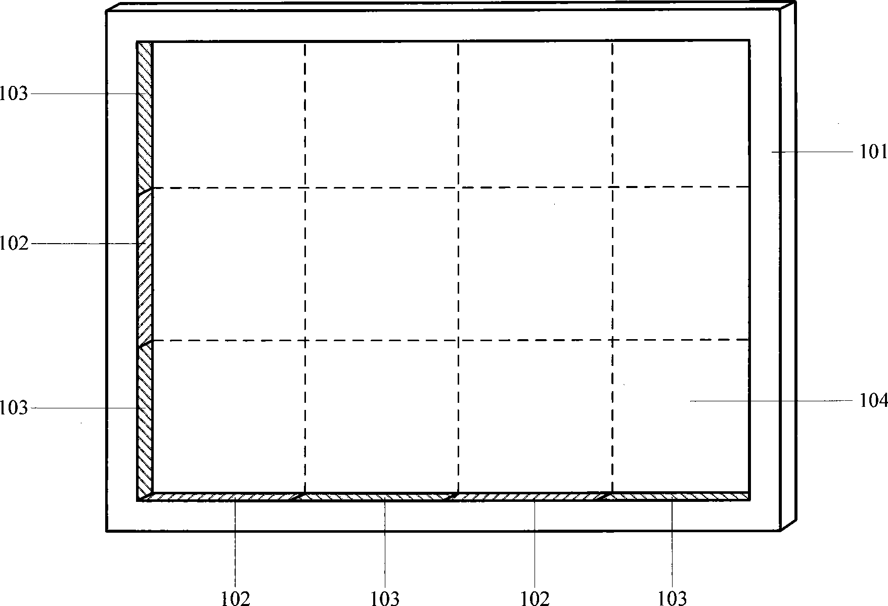
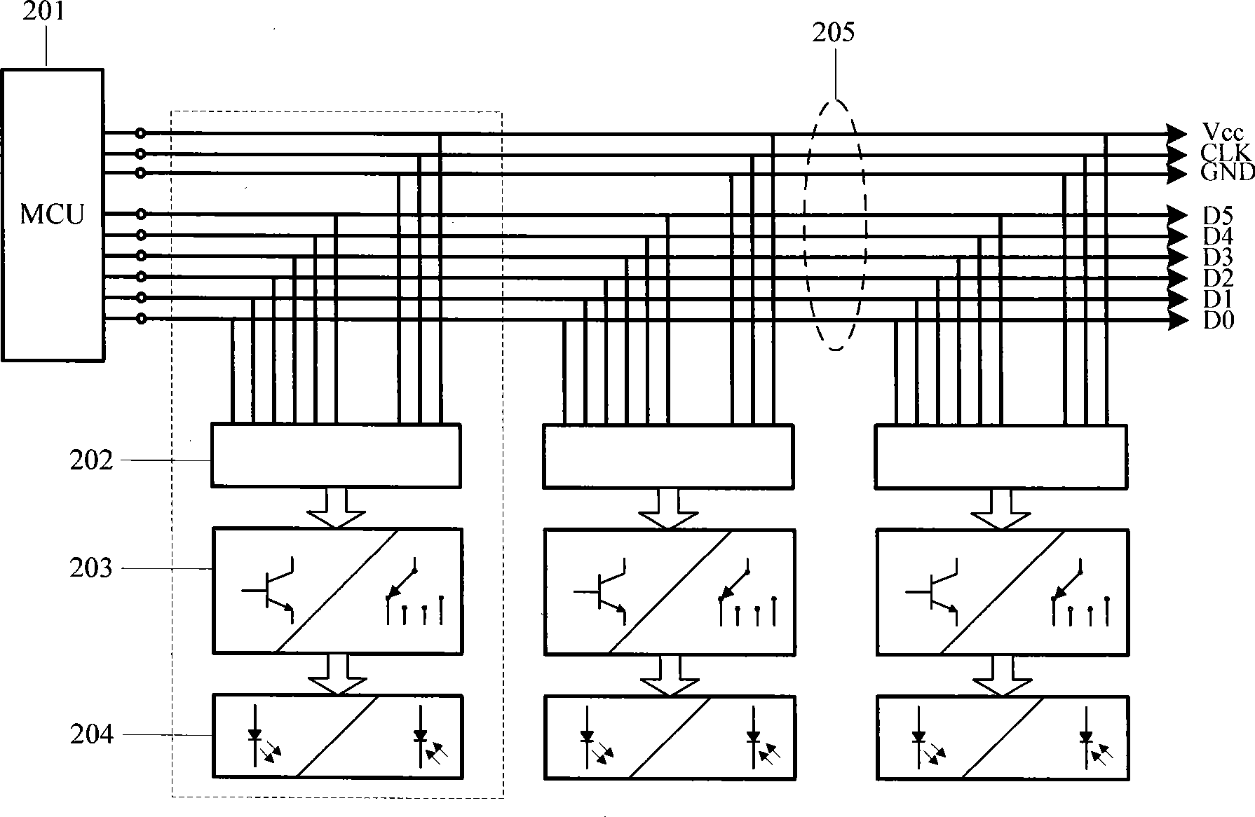
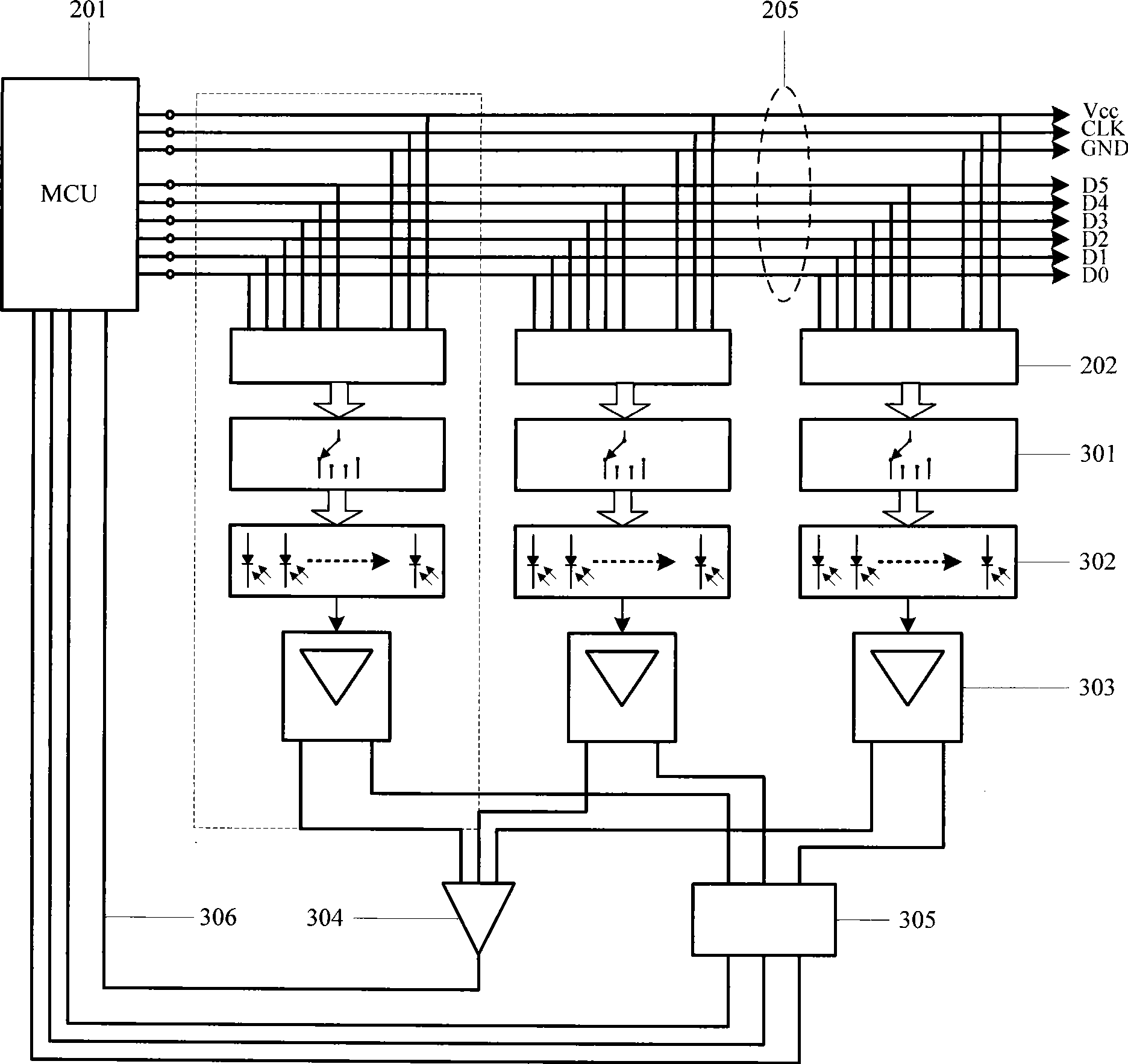
[0016] The present invention divides the array of infrared emitting and receiving pairs of tubes into several modules in the arrangement direction. Generally, the modules containing the same number of infrared emitting and receiving pairs of tubes are numbered for later identification of which group is output. It is used for detecting signals, and the simplest way is that the circuit structure inside the module is the same. Then use polarizers with opposite (perpendicular) polarization directions installed in front of the working surface (transmitting surface or receiving surface) of the array of infrared emitting tubes and receiving tubes (collectively referred to as infrared elements) to block adjacent modules from emitting infrared rays at the same time The scattered light of the luminescent tube interferes with the receiving tube ...


PUM


Abstract

A parallel scanning system of an infrared touch screen which uses polaroid sheets comprises an infrared element, infrared filter windows, corresponding drive circuits and corresponding signal processing circuits as well as a microcontroller system. The invention is characterized in that the infrared element is divided into a plurality of modules that are numbered; the infrared filter windows in front of each module are internally provided with the polaroid sheets with the same polaroid direction; the polaroid directions of the polaroid sheets in front of two neighboring modules on the same frame are reverse; the drive circuits in each module are the same; the input ends thereof after being connected in parallel are connected with the output ends of the address drive data of the microprocessor system; the module also comprises an infrared signal processing circuit; the detection signal output end of the infrared signal processing circuit is connected with the microprocessor system through a group symbol coder or directly connected with the microprocessor system. The invention divides the touch screen into a plurality of detection areas of small areas and carries out detection, thereby extensively improving the response speed of the touch screen. Besides, as the structures of the modules are the same, the design, manufacture and maintenance costs of the touch screen are reduced.

Description

technical field [0001] The invention relates to an improvement scheme of an optical path and a circuit structure of an infrared scanning detection system in an infrared touch screen, and belongs to the technical field of touch screens in computer multimedia technology. technical background [0002] In the existing infrared touch screen, for the scanning detection method of the touch object on the surface to be detected, a group of infrared emitting tube arrays and corresponding infrared receiving tube arrays installed on the frame of the infrared touch screen are used, through logic circuits and analog The circuit is sequentially driven by the scanning address information generated by the microcontroller system inside the touch screen, and gates each pair of infrared emitting and receiving tubes in the array to realize the emission and reception of infrared rays used to detect touch objects. [0003] Since the prior art drives and gates the infrared elements in a single cycl...

Claims


Application Information

Patent Timeline
Patent Type & Authority Applications(China)
IPC IPC(8): G06F3/042
Inventor 叶新林刘中华刘新斌刘建军
Owner BEIJING UNITOP NEW TECH CO LTD
Why Eureka
Try Eureka