Static coil type micromechanical electromagnetic vibration energy collector based on frequency boost conversion

A technology of energy harvester and fixed circle miniaturization, which is applied in the direction of electromechanical devices and electrical components, can solve problems such as the limitation of induced electromotive force, the complexity of device manufacturing process, and the change of cantilever beam stiffness, so as to achieve high output voltage and output power, and realize batch production The effects of modernized production and high frequency adaptability

Active Publication Date: 2009-04-01
SHANGHAI JIAO TONG UNIV
View PDF0 Cites 15 Cited by
  • Summary
  • Abstract
  • Description
  • Claims
  • Application Information

AI Technical Summary

Problems solved by technology

Although this design can achieve up-conversion, but because the coil is made on a movable platform, the device manufacturing process is too complicated and it is difficult to make a multi-layer coil
Since the permanent magnet passes through the plane where the coil is located, the permanent magnet occupies most of the area. When the device area is constant, the size of the coil winding is limited, including the number of turns and the length of the winding. Therefore, the induced electromotive force that the coil can generate is also limited. limit
At the same time, since the permanent magnet occupies most of the area, the size and shape of th

Method used


Image

  • Static coil type micromechanical electromagnetic vibration energy collector based on frequency boost conversion
  • Static coil type micromechanical electromagnetic vibration energy collector based on frequency boost conversion

Examples


Embodiment Construction

[0033] The embodiments of the present invention are described in detail below in conjunction with the accompanying drawings: this embodiment is implemented on the premise of the technical solution of the present invention, and detailed implementation methods and specific operating procedures are provided, but the protection scope of the present invention is not limited to the following the described embodiment.

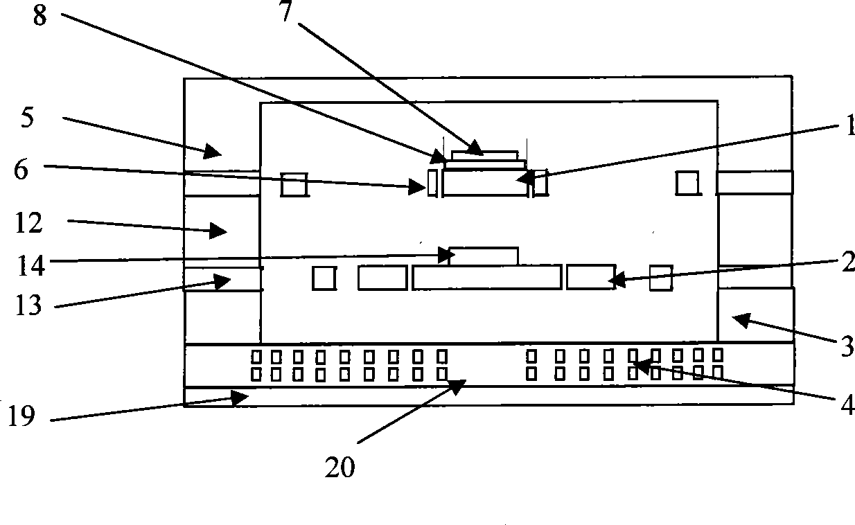
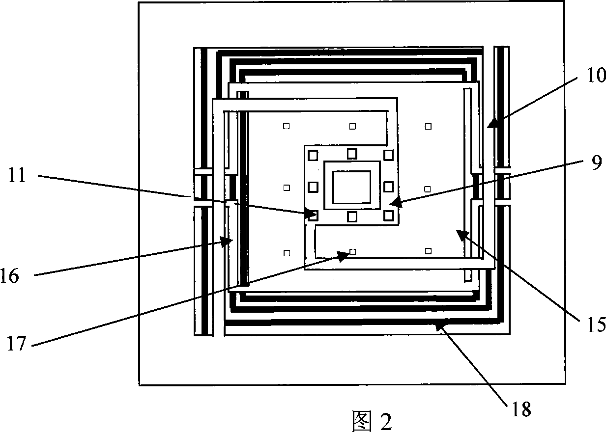
[0034] Such as figure 1 As shown, this embodiment includes: a low-frequency vibration pickup table 1 , a high-frequency resonance table 2 , a spacer 3 and an induction coil 4 . The high-frequency resonance table 2 is located above the induction coil 4 , the high-frequency resonance table 2 is located below the low-frequency vibration pickup table 1 , and the gasket 3 is located between the high-frequency resonance table 2 and the induction coil 4 .

[0035] Such as figure 1 , 2, the low frequency pickup table 1 includes: a top cover 5, a metal plane spring 6, a vibr...


PUM

PropertyMeasurementUnit
Thicknessaaaaaaaaaa
Widthaaaaaaaaaa
Depthaaaaaaaaaa

Abstract

The invention discloses a fixed-coil micro mechanical magnetic vibration energy collector basing on upconversion in the field of new energy technology. The collector comprises a vibration pickup station with low frequency, a resonance station with high frequency, a spacer and an induction coil; the vibration pickup station with low frequency comprises a coping, an upper-layer flat spring and a start-oscillation permanent magnet and/or a soft magnet. The upper-layer flat spring is fixed at the edge of the groove at the coping, the upper-layer flat spring comprises an upper-layer central platform and the surrounded upper-layer cantilever beam, the start-oscillation permanent magnet and/or the soft magnet are fixed on the upper-layer central platform; the resonance station with high frequency comprises frames, a lower-layer flat spring and a resonance permanent magnet, the lower-layer flat spring is fixed on the frames, the lower-layer flat spring comprises a lower-layer central platform and the surrounded lower-layer cantilever beam, and the resonance permanent magnet is fixed at the lower-layer central platform; the spacer is located between the resonance station with high frequency and the induction coil; the winding of the induction coil is fixed at the insulated underlay which is fixed under the spacer without movement. The conversion rate of the invention is high, and manufacture of batches and integration can be realized.

Description

technical field [0001] The invention relates to a collector in the field of micro-electromechanical technology, in particular to a fixed-coil micro-mechanical electromagnetic vibration energy collector based on up-frequency conversion. Background technique [0002] With the maturity of microelectronics technology, high technologies such as automotive sensing, embedded systems, RFID (radio frequency identification) and wireless sensor networks are developing rapidly. These technologies require power supply components to have the characteristics of small size, light weight, and long life. The main power supply methods at present are batteries and wired power supply. The battery life is short, the storage energy is limited, and compared with the above devices, the volume and mass are large. When the working life is more than a few years, the battery-based power supply method is difficult to meet the power supply requirements of sensor nodes. Wireless communication and various...

Claims


Application Information

Patent Timeline
IPC IPC(8): H02K35/02
Inventor 戴旭涵赵小林丁桂甫
Owner SHANGHAI JIAO TONG UNIV
Why Eureka
Try Eureka