
High-gradient magnetic separation machine

A high-gradient magnetic separator and sorting technology, applied in high-gradient magnetic separators and other directions, to achieve the effects of reducing energy consumption, solving magnetic blockage, and improving service life

Inactive Publication Date: 2009-04-08
GUANGZHOU RES INST OF NON FERROUS METALS +1
View PDF2 Cites 5 Cited by
  • Summary
  • Abstract
  • Description
  • Claims
  • Application Information

AI Technical Summary

Problems solved by technology

[0006] The purpose of the present invention is to solve the above-mentioned problems in the prior art, and provide a high-gradient magnetic field that can effectively solve the problem of magnetic blockage and conveniently adjust the magnetic field strength, ensure convenient maintenance in actual production, and greatly reduce energy consumption. machine selection

Method used


Image

  • High-gradient magnetic separation machine
  • High-gradient magnetic separation machine
  • High-gradient magnetic separation machine

Examples


Embodiment Construction

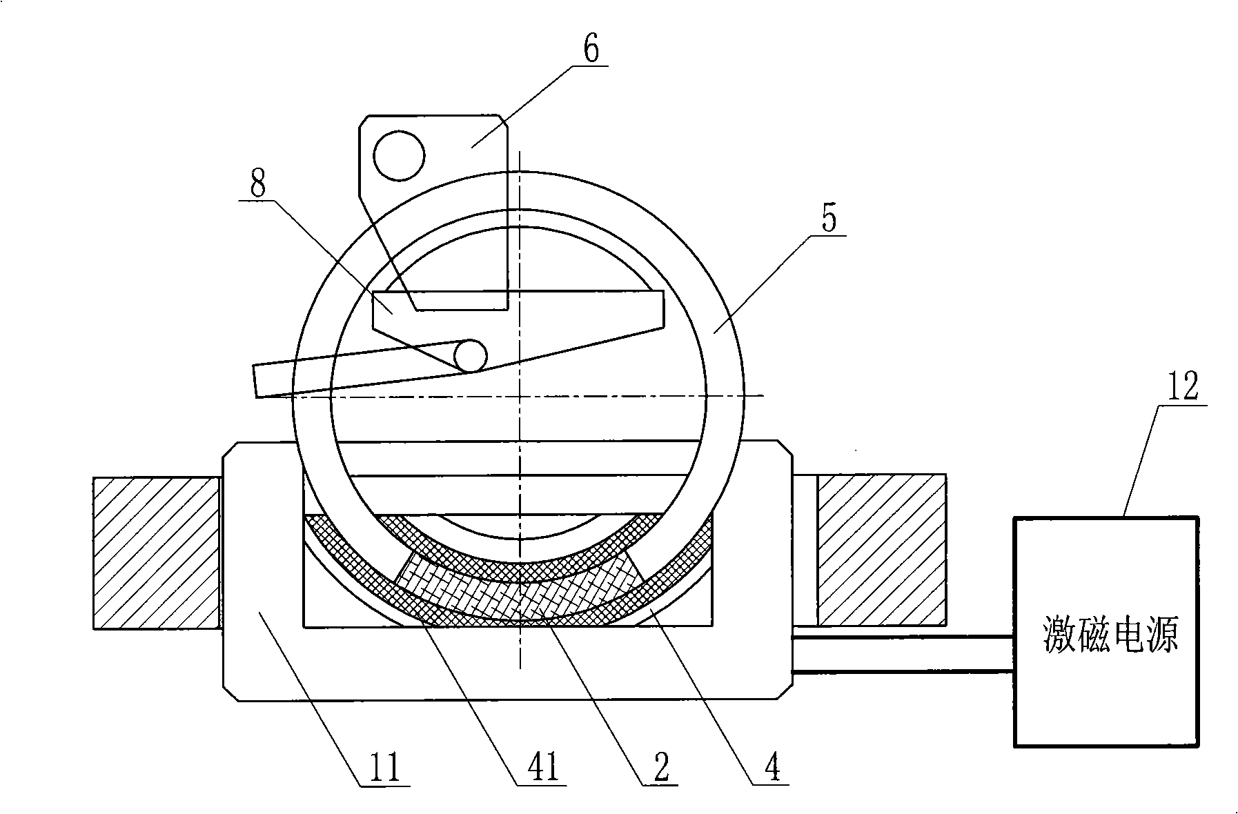
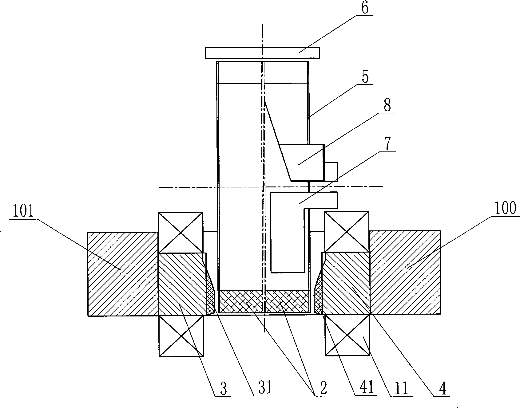
[0015] Such as Figure 1 ~ Figure 2 As shown, a kind of high gradient magnetic separator described in the present invention comprises sorting ring and its driving device, ore feeding device 7, concentrate gas-water unloading device and concentrate collecting device 8, wherein the sorting ring includes a swivel 5 and the magnetic gathering medium stack 2 installed on the swivel 5, the left yoke 3, the left magnet 31, the right yoke 4, and the right magnet 41 that are positioned at the left and right sides of the swivel 5, are characterized in that they also include devices on the The charging and demagnetizing device below the swivel can respectively charge and demagnetize the left magnet 31 and the right magnet 41. Connect the excitation power supply 12. Among them, the swivel ring 5 is a vertical double-ring structure, and a turntable connecting the double rings as a whole is arranged between the rings. A shaft sleeve with bearings is arranged in the turntable. The medium p...


PUM


Abstract

The invention discloses a high gradient magnetic separator, which comprises a separation ring and a driving device thereof, an ore feeding device, a concentrated ore discharging device and a concentrated ore collecting device, wherein the separation ring comprises a rotating ring and a concentrated magnetic medium pack, a left magnetic yoke, a left magnet, a right magnetic yoke, a right magnet, a front magnetic yoke, a rear magnetic yoke, and a magnetizing and demagnetizing device which consists of magnetic coils and a magnetizing power source and can perform magnetizing and demagnetizing treatment on the left magnet and the right magnet respectively. The high gradient magnetic separator smartly combines a permanent magnet and a magnetizing power source to form a background magnetic field of the separator, so the high gradient magnetic separator can conveniently perform magnetizing and demagnetizing treatment on the left magnet and the right magnet according to the required value of the background magnetic field and then perform effective separation on ores after canceling the magnetizing power source when in work, and can perform demagnetizing treatment on an upper magnet and a lower magnet when in assembly and maintenance so as to solve the magnetic blockage problem. The high gradient magnetic separator can greatly reduce the energy consumption, and fully ensure convenient maintenance in practical production.

Description

technical field [0001] The invention relates to a magnetic separator for ore dressing, in particular to a high-gradient magnetic separator. Background technique [0002] The proposal of high gradient magnetic separation theory has brought a qualitative leap to the field of magnetic separation, increasing the types of minerals that can be magnetically separated, and widening the upper and lower limits of particle size. Early high-gradient magnetic separators are periodic, also known as magnetic filters, and this type of equipment is widely used in occasions with extremely low magnetic content and very fine particle size. The continuous high gradient magnetic separators that appeared immediately include electromagnetic flat ring strong magnetic high gradient magnetic separators, permanent magnet and electromagnetic double vertical ring high gradient magnetic separators. Electromagnetic flat-ring high-gradient magnetic separator is easy to cause mechanical blockage because the...

Claims


Application Information

Patent Timeline
Patent Type & Authority Applications(China)
IPC IPC(8): B03C1/025
Inventor 汤玉和朱远标张军叶富兴张红英廖锦陈俊明吴城材刘联邦林恬盛
Owner GUANGZHOU RES INST OF NON FERROUS METALS
Learn More