
Novel method for discharging residual winding from sleeve barrel

A technology of residual coils and sleeves, which is applied in the field of plate and strip finishing devices, and can solve the problems of large footprint, long auxiliary time, and high manufacturing costs

Inactive Publication Date: 2009-04-08
CHINA NON-FERROUS METALS PROCESSING TECH CO LTD
View PDF0 Cites 11 Cited by
  • Summary
  • Abstract
  • Description
  • Claims
  • Application Information

AI Technical Summary

Problems solved by technology

[0002] At present, two sets of separate devices are usually used for loading sleeves and unloading residual coils in non-ferrous metal stretch-bending straightening units, which are the sleeve loading device and the residual coil unloading device. The inevitable result of this is: high manufacturing costs, accounting for The land area is large, and the auxiliary time in the production process is long

Method used


Image

  • Novel method for discharging residual winding from sleeve barrel

Examples


Embodiment Construction

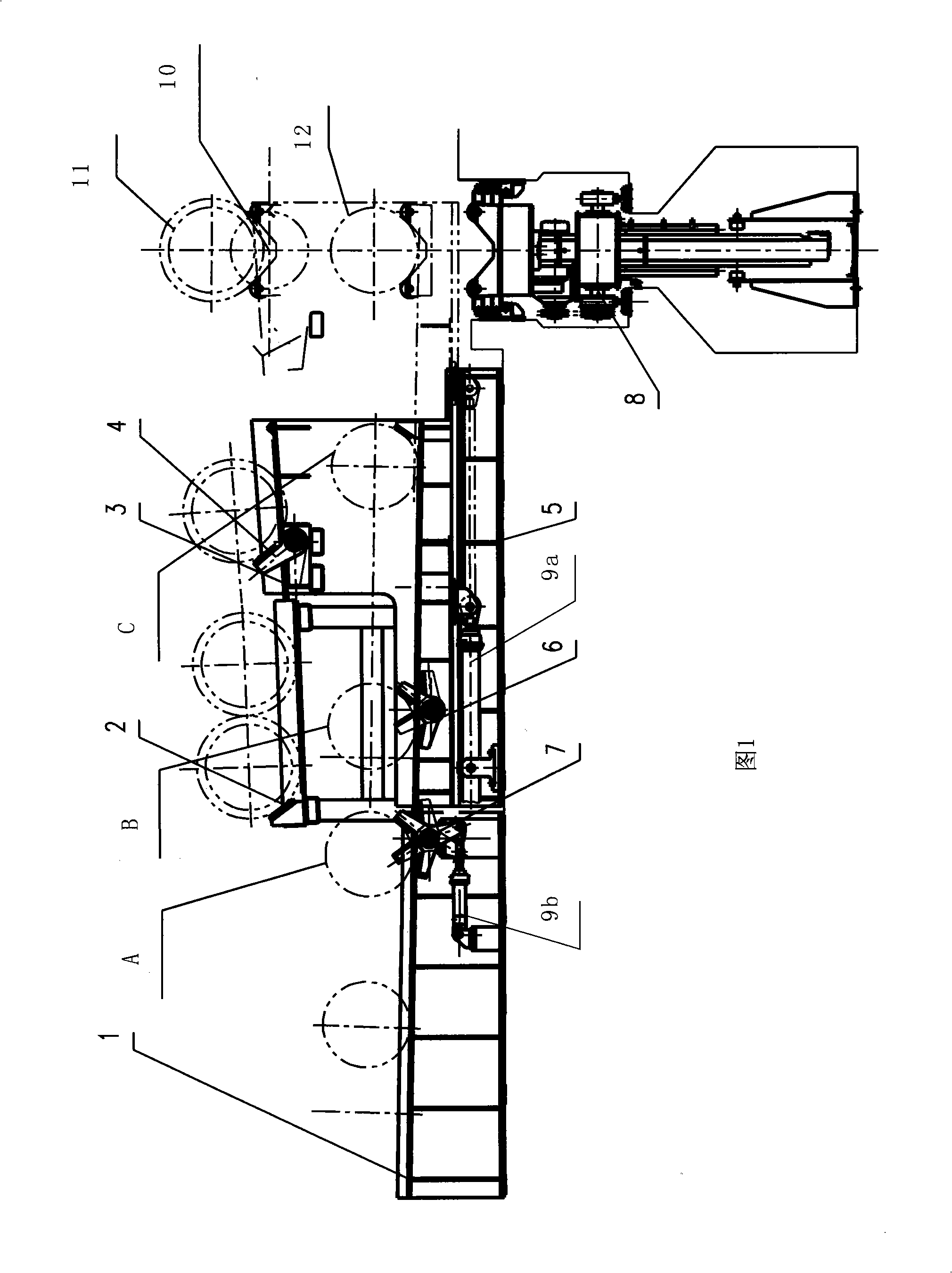
[0024] As shown in Figure 1: A new method for unloading residual rolls on the upper sleeve is to combine the upper sleeve device and the unloading residual roll device into one, and its manufacturing method is as follows:

[0025] A double-layer structure is adopted, the lower layer is the upper sleeve device, and the upper layer is the unloading device; one end of the upper sleeve device and the unloading device is a fixed sleeve storage table (1) and a remnant stacking rack (2) , the middle is a movable carriage (3), the other end is an unloading trolley (8), the bottom of the carriage is slidingly connected with the base (5); the carriage (3) is composed of two layers, and the upper layer of the carriage can be temporarily unloaded For the remnant roll, the lower layer of the carriage can temporarily place the sleeve to be loaded, and the upper and lower layers of the carriage are respectively provided with shift fork a.(4) and shift fork b(6) to move the remnant roll or sle...


PUM


Abstract

The invention discloses a method for a novel upper-sleeve coil stripper, which integrates an upper sleeve device and a coil stripper device into a whole. The method is as follows: the lower layer of the novel upper-sleeve coil stripper is provided with the upper sleeve device; one end of the novel upper-sleeve coil stripper is provided with a fixed sleeve storage platform (1) and a coil stripper stacking frame (2); the sleeve storage platform is provided with a striking fork c(7) for striking a sleeve; the middle of the novel upper-sleeve coil stripper is provided with a movable slide block (3) which is double-layered; a misshapen coil can be temporarily placed on the upper layer of the slide block, and the sleeve can be temporarily placed on the lower layer of the slide block; striking forks are arranged on the upper layer and the lower layer of the slide block respectively; the other end of the upper-sleeve coil stripper is provided with a coil stripping bogie (8); and the bottom of the slide block is slidably connected with a pedestal (5). The work flow of the novel upper-sleeve coil stripper is as follows: the coil stripping bogie (8) unloads the misshapen coil from a coiler (10); the slide block (3) moves to place the misshapen coil on the upper layer of the slide block; a striking fork b of the slide block strikes the sleeve (12) which is placed on the lower layer of the slide block from the B position to the C position; and the coil stripping bogie (8) moves upwards to support the sleeve. The method can well solve the problems, and has low manufacturing cost, small floor space, and short auxiliary time during the production process.

Description

technical field [0001] The invention relates to the technical field of finishing devices for plates and strips, and is mainly used for a novel method for unloading remnant coils on upper sleeves in nonferrous metal stretch-bending straightening units. Background technique [0002] At present, two sets of separate devices are usually used for loading sleeves and unloading remnants in non-ferrous metal stretch-bending straightening units, namely the sleeve loading device and the remnant coil unloading device. The inevitable result of this is: high manufacturing costs, accounting for The land area is large, and the auxiliary time in the production process is long. Contents of the invention [0003] In order to solve the above-mentioned problems, the present invention provides a new method for unloading residual rolls on the upper sleeve, which can better solve the above-mentioned problems. Its manufacturing cost is low, the floor space is small, and the auxiliary time in the ...

Claims


Application Information

Patent Timeline
IPC IPC(8): B21C47/24
Inventor 刘浩如张美娟
Owner CHINA NON-FERROUS METALS PROCESSING TECH CO LTD
Learn More