Converted transverse wave detection point static correction method and device

A technology for converting shear wave and receiver points, applied in the field of static correction methods and devices for converted shear wave receiver points, which can solve problems such as inconsistent geological conditions, difficulty in layer picking, and limited application range, so as to improve imaging quality and accuracy, solve Effect of converting wave static correction problems

Pending Publication Date: 2021-02-02
BC P INC CHINA NAT PETROLEUM CORP +1
View PDF8 Cites 0 Cited by
  • Summary
  • Abstract
  • Description
  • Claims
  • Application Information

AI Technical Summary

Problems solved by technology

[0004] However, the prerequisite for the application of this method is that the geological structure in the work area is simple and gentle, and the signal-to-noise ratio of the converted shear wave data is high. In the superimposed section of the common receiver point, the event of the marker horizon can be traced continuously
Otherwise, difficulty in layer picking and picking errors are likely to occur in the process of human-computer interaction layer picking, which will lead to large errors in the process of calculating the static correction amount
Coupled with the low signal-to-noise ratio and poor imaging quality of the converted shear wave, it is impossible to control the structure, and then it does not conform to the actual geological conditions and cannot meet the data processing requirements.
Therefore, the scope of application of existing technical methods is limited

Method used


Image

  • Converted transverse wave detection point static correction method and device
  • Converted transverse wave detection point static correction method and device
  • Converted transverse wave detection point static correction method and device

Examples


Embodiment Construction

[0052] Embodiments of the present invention provide a static correction method and device for converted shear wave detection points.

[0053] The following will clearly and completely describe the technical solutions in the embodiments of the present invention with reference to the accompanying drawings in the embodiments of the present invention. Obviously, the described embodiments are only some, not all, embodiments of the present invention. Based on the embodiments of the present invention, all other embodiments obtained by persons of ordinary skill in the art without creative efforts fall within the protection scope of the present invention.

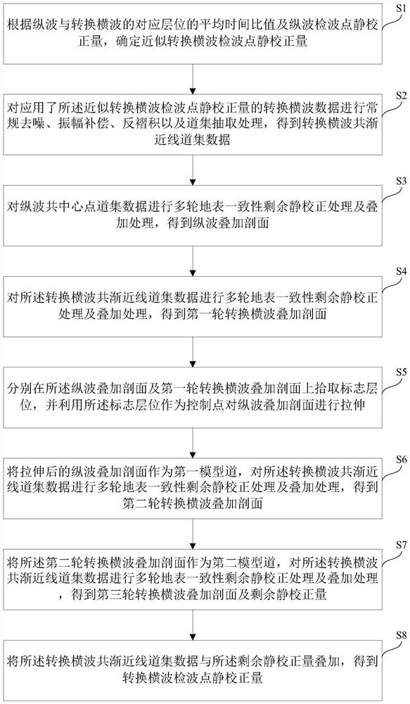
[0054] Such as figure 1 Shown is a flow chart of a static correction method for converted shear wave detection points according to an embodiment of the present invention. The method shown in the figure includes:

[0055] Step S1, according to the average time ratio of the corresponding horizon of the longitudinal wave and the conve...


PUM


Abstract

The invention provides a converted transverse wave detection point static correction method and device. The method comprises the following steps: determining an approximate conversion transverse wavedetection point static correction value according to an average time ratio and a longitudinal wave detection point static correction value; performing trace gather extraction processing on the converted transverse wave data to obtain common asymptotic line trace gather data; performing multiple rounds of earth surface consistency residual static correction processing and superposition processing on the longitudinal wave common midpoint gather data; processing the common asymptote gather data to obtain a first round of converted transverse wave superposition profile; picking up mark layers on the longitudinal wave superposition section and the first round of conversion transverse wave superposition section, and stretching the longitudinal wave superposition section; taking the stretched longitudinal wave superposed section as a first model channel to obtain a second round of converted transverse wave superposed section; repeating the processing to obtain a third round of converted transverse wave superposition profile and a residual static correction value; and superposing the approximate converted transverse wave detection point static correction value with the third round of residual static correction value to obtain a final converted transverse wave detection point static correction total amount.

Description

technical field [0001] The invention relates to the technical field of converted shear wave seismic data processing, in particular to a static correction method and device for converted shear wave receiver points. Background technique [0002] In the processing of converted shear wave seismic data, the most critical and basic processing link is the calculation of the static correction of converted shear wave receiver points. According to the dynamic characteristics of the converted shear wave, it can be known that the converted shear wave does not propagate in the fluid, but only in the rock skeleton, so its propagation speed is mainly determined by the rock skeleton. However, the P-wave static correction calculated by taking the shallow water surface as the top boundary of the high-velocity layer is naturally not suitable for converting the S-wave. In addition, the shear wave velocity is lower than the longitudinal wave velocity, and there is a difference between the under...

Claims


Application Information

Patent Timeline
Patent Type & Authority Applications(China)
IPC IPC(8): G01V1/36
CPCG01V1/362G01V2210/53
Inventor 王栋杨海涛王鸿燕钱忠平吕文彪
Owner BC P INC CHINA NAT PETROLEUM CORP
Why Eureka
Try Eureka