Angle steel eyelet work product line

A production line and angle steel technology, applied in the direction of piercing tools, metal processing equipment, feeding devices, etc., can solve the problems of inability to realize automatic production, difficult processing, error-prone, etc., and achieve high production efficiency of the whole machine, stable movement, and improved The effect of punching accuracy

Inactive Publication Date: 2009-04-08
浙江博雷重型机床制造有限公司
View PDF0 Cites 32 Cited by
  • Summary
  • Abstract
  • Description
  • Claims
  • Application Information

AI Technical Summary

Problems solved by technology

However, the above-mentioned punching equipment can only realize the continuous punching of angle steel in one direction (x-axis). Therefore, when multiple punching positions of angle steel are on the punching surface, not only the direction of x-axis changes, but also the direction of y-axis When a change occurs, manual positioning is requi

Method used


Image

  • Angle steel eyelet work product line
  • Angle steel eyelet work product line
  • Angle steel eyelet work product line

Examples


Embodiment 1

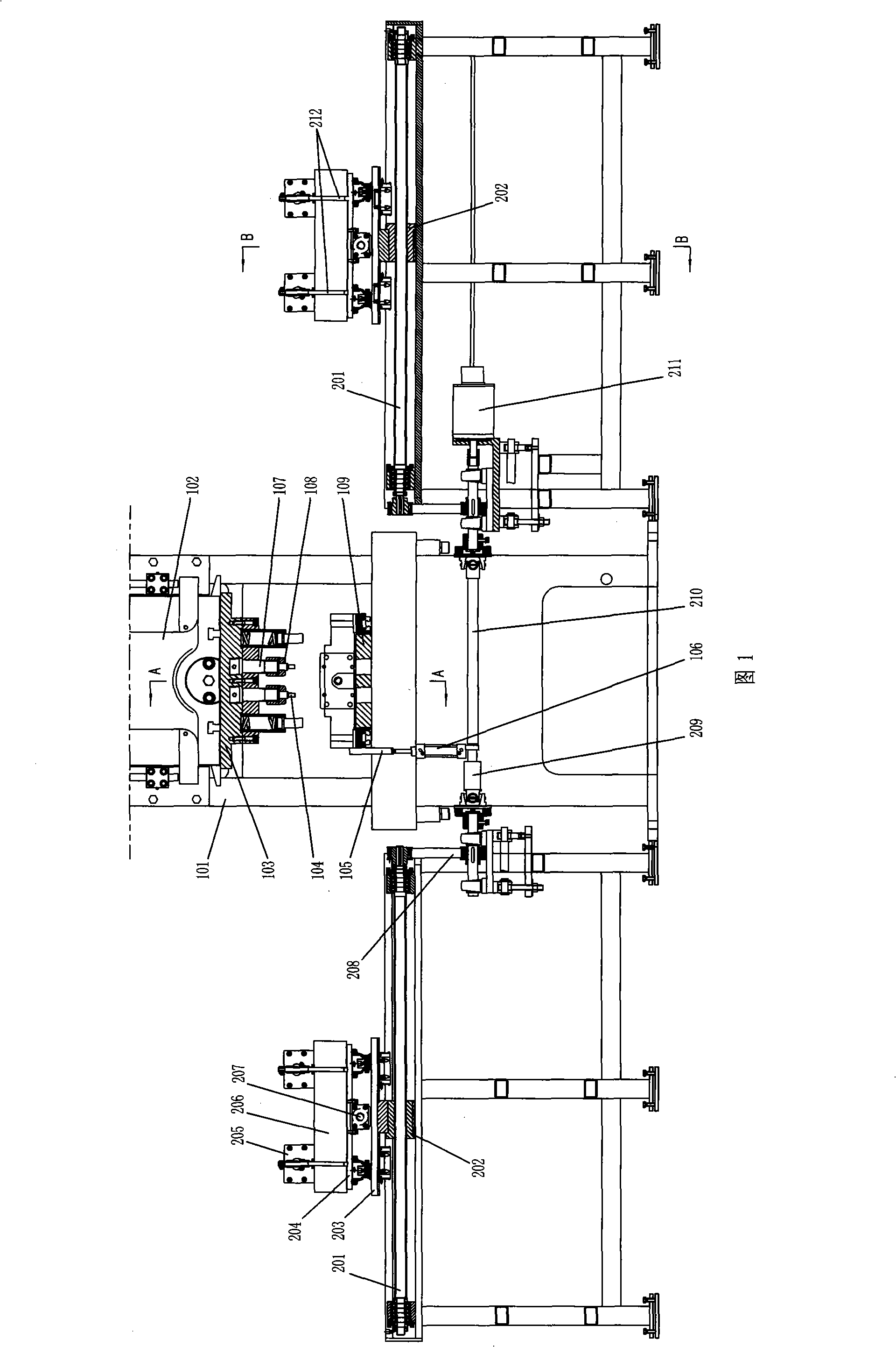
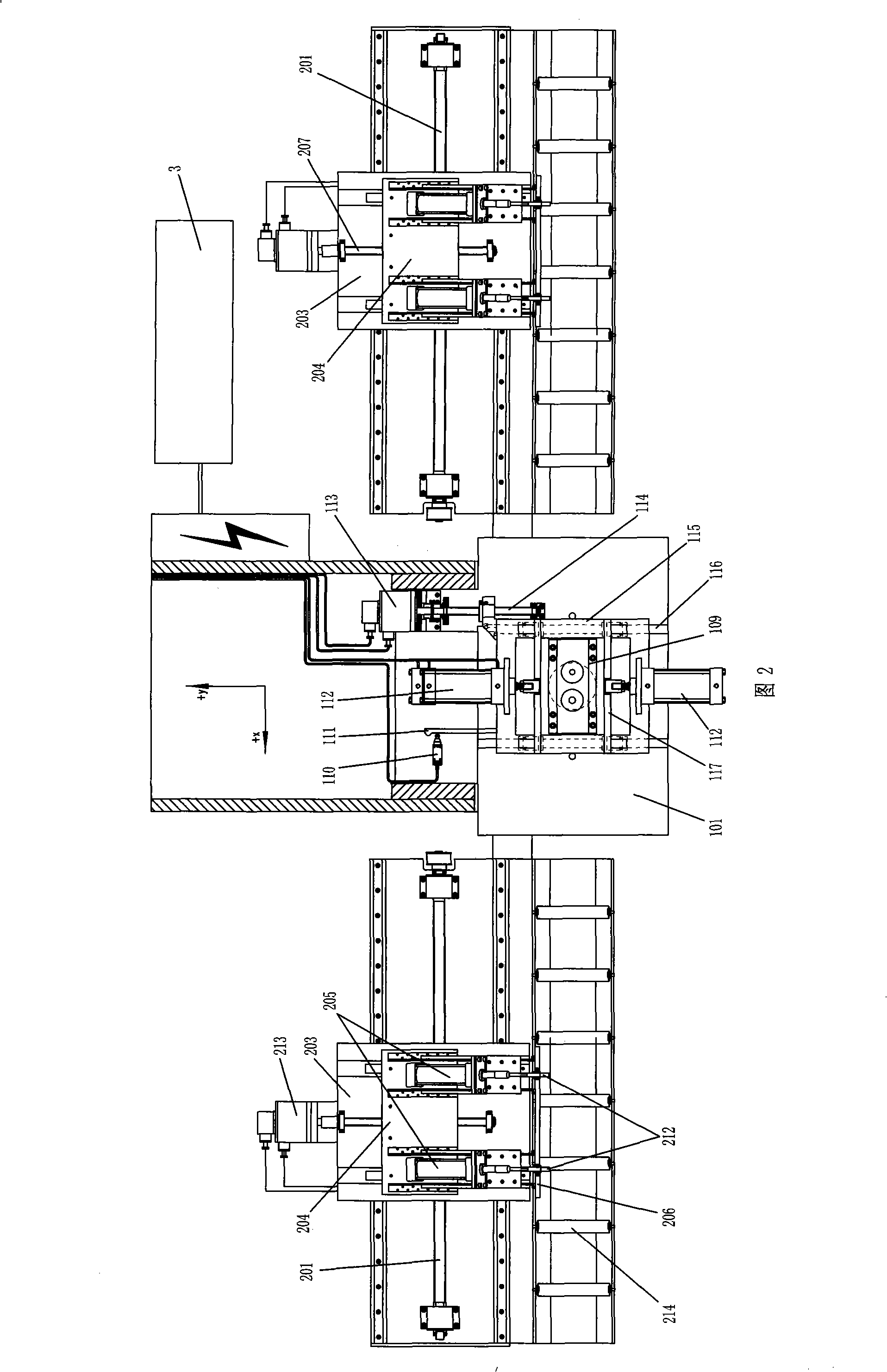
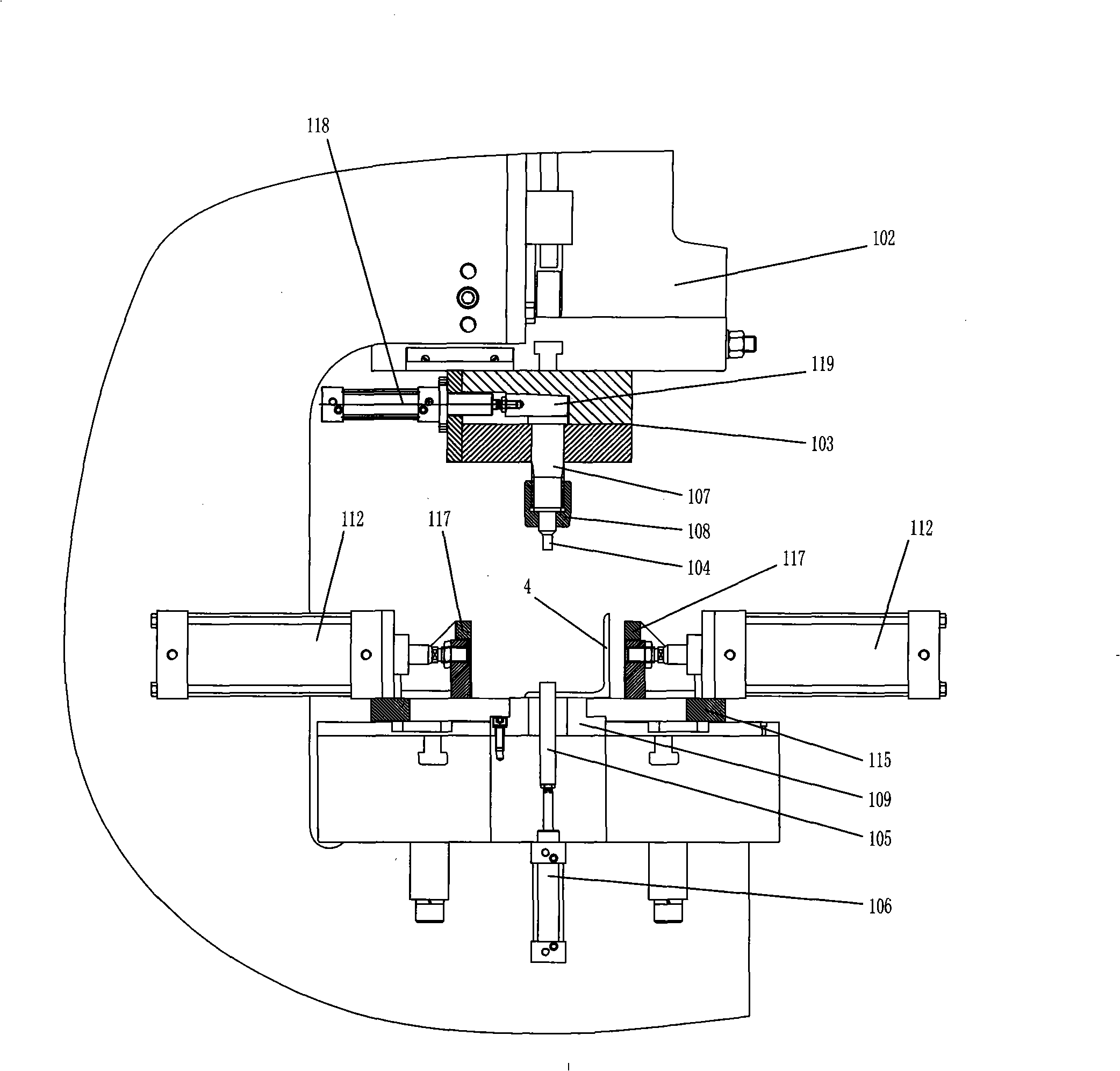
[0021] A kind of angle steel punching production line as shown in Fig. 1, Fig. 2, comprises press 101, upper die 103 is set on the slide block 102 of press 101, and lower die 109 is set on the operation table of press 101, described press Clamping and feeding devices for the angle steel workpiece 4 are arranged on both sides of the workbench of 101. The clamping and feeding devices include a workbench, and the workbench is provided with a conveying roller 214 for horizontally conveying the angle steel. One side of the conveying roller 214 There is a transverse feed carriage 203, which is horizontally slidably connected to the workbench. The plate 203 is fixedly connected to the screw cover 202, and the transverse screw 201 is connected to the transverse feed motor 211 on the workbench; the transverse feed carriage 203 is longitudinally slidably connected with a longitudinal feed carriage 204 , the turret on the horizontal feed carriage 203 is provided with a longitudinal screw...


PUM


Abstract

The invention discloses a production line for punching angle iron. A transverse feed device and a transverse positioning device are used to realize the feed displacement and the positioning of an angle iron work piece along the transverse direction(the X axis); a vertical feed device, a vertical displacement device and a vertical positioning device which are matched with each other are used to realize the displacement and the positioning of the angle iron work piece along the vertical direction(the Y axis); and in the whole process of punching, after the angle iron work piece is put on the production line for punching, the clipping, feed, displacement, accurate positioning and punching are automatically realized, thereby not only realizing the automatic accurate positioning and continuous punching on any position of a punching face of the angle iron along the X and the Y axes, but also greatly improving the punching accuracy, production efficiency and processing stability and reliability.

Description

technical field [0001] The invention belongs to the field of punching equipment, in particular to a production line equipment for punching angle steel, especially iron tower angle steel. Background technique [0002] In the existing angle steel punching technology, most of the angle steel is manually clamped on the punching press for punching, and the positioning of the punching position depends on manual determination. Although there are also manufacturers who connect simple feeding devices to the punching press to realize the angle steel Continuous punching in one direction (x-axis), the punching distance is controlled manually or automatically by the feeding device. However, the above-mentioned punching equipment can only realize the continuous punching of angle steel in one direction (x-axis). Therefore, when multiple punching positions of angle steel are on the punching surface, not only the direction of x-axis changes, but also the direction of y-axis When a change oc...

Claims


Application Information

Patent Timeline
IPC IPC(8): B21D28/32B21D43/00B21D28/34
Inventor 高尔荣
Owner 浙江博雷重型机床制造有限公司
Why Eureka
Try Eureka