
Independent oil supply structure for oil recess inside and outside primary shaft gathering ring bearing of high-speed machine tool

A technology of machine tool spindle and floating ring bearing, which is applied in metal processing machinery parts, maintenance and safety accessories, metal processing equipment, etc., can solve the problems of limited high-speed performance, short service life, shaft holding, etc., and achieves a simple and reasonable overall structure. The effect of high operating speed and low manufacturing cost

Inactive Publication Date: 2011-01-26
吴寿麟
View PDF0 Cites 0 Cited by
  • Summary
  • Abstract
  • Description
  • Claims
  • Application Information

AI Technical Summary

Problems solved by technology

Rolling bearings are the main supporting structure of machine tool spindles at present. They have the advantages of high speed, simple structure, mass production, and can be replaced as a whole during maintenance. , there are inevitably friction wear and fatigue wear, and the service life is short. After working for a period of time, the main shaft must be disassembled for maintenance, and the maintenance and assembly process of the main shaft is complicated, which requires a high level of maintenance personnel. Repair or replace the main shaft It takes a lot of time and cost, which has a negative impact on the production efficiency of the machine tool; second, because the rolling bearing relies on the rigid contact of a limited number of rolling elements to provide bearing capacity, the stress at the place where the inner and outer raceways of the bearing are in contact with the balls is very high. Where there is no contact, the stress is small, and there must be uneven deformation in the circumferential direction. Therefore, the machine tool spindle supported by rolling bearings is not suitable for occasions that require very high machining accuracy and surface finish, such as precision grinding machines, Precision Boring Machine etc.
[0006] However, the existing floating ring bearing high-speed spindle structure has obvious disadvantages
The oil in the existing floating ring oil chamber generally adopts the method of directly supplying oil from the bearing oil chamber, or although independent oil supply is considered, it does not avoid the influence of the high-temperature oil flow in the outer layer
Since the oil in the outer oil chamber has a high temperature rise when the main shaft rotates at high speed, when the oil with high temperature enters the floating ring oil chamber, it will cause the main shaft to heat up and expand, and a "shaft holding" accident may occur; at the same time, the temperature is too high High, will cause the viscosity of the lubricating oil to decrease, thereby reducing the rigidity of the spindle system
These shortcomings limit the full play of high-speed performance
The floating ring bearing high-speed spindle adopting the above-mentioned oil supply method has not been fully applied in machine tools due to the above-mentioned defects, and the mass production of the floating-ring bearing high-speed spindle as a unit functional component has not been realized.

Method used


Image

  • Independent oil supply structure for oil recess inside and outside primary shaft gathering ring bearing of high-speed machine tool
  • Independent oil supply structure for oil recess inside and outside primary shaft gathering ring bearing of high-speed machine tool
  • Independent oil supply structure for oil recess inside and outside primary shaft gathering ring bearing of high-speed machine tool

Examples


Embodiment Construction

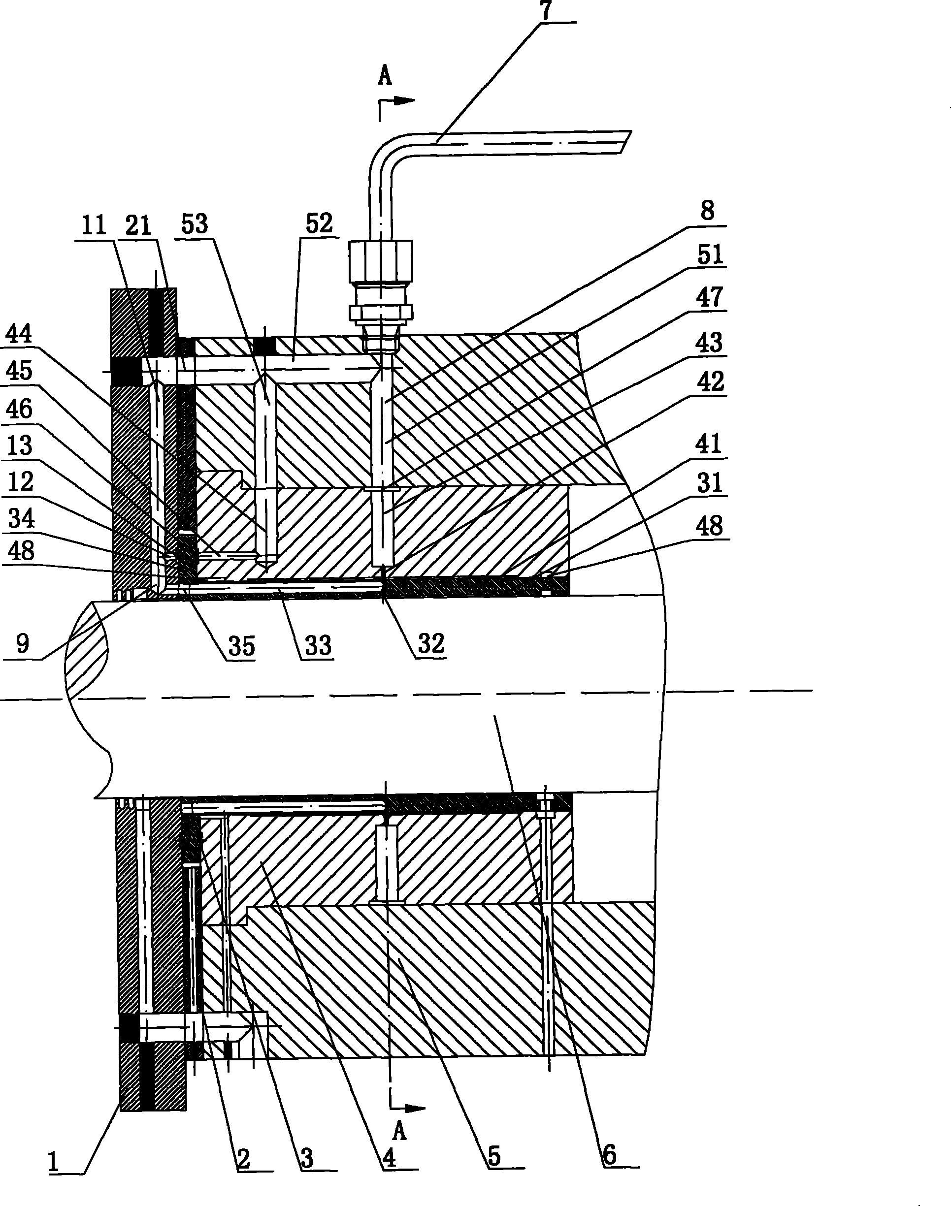
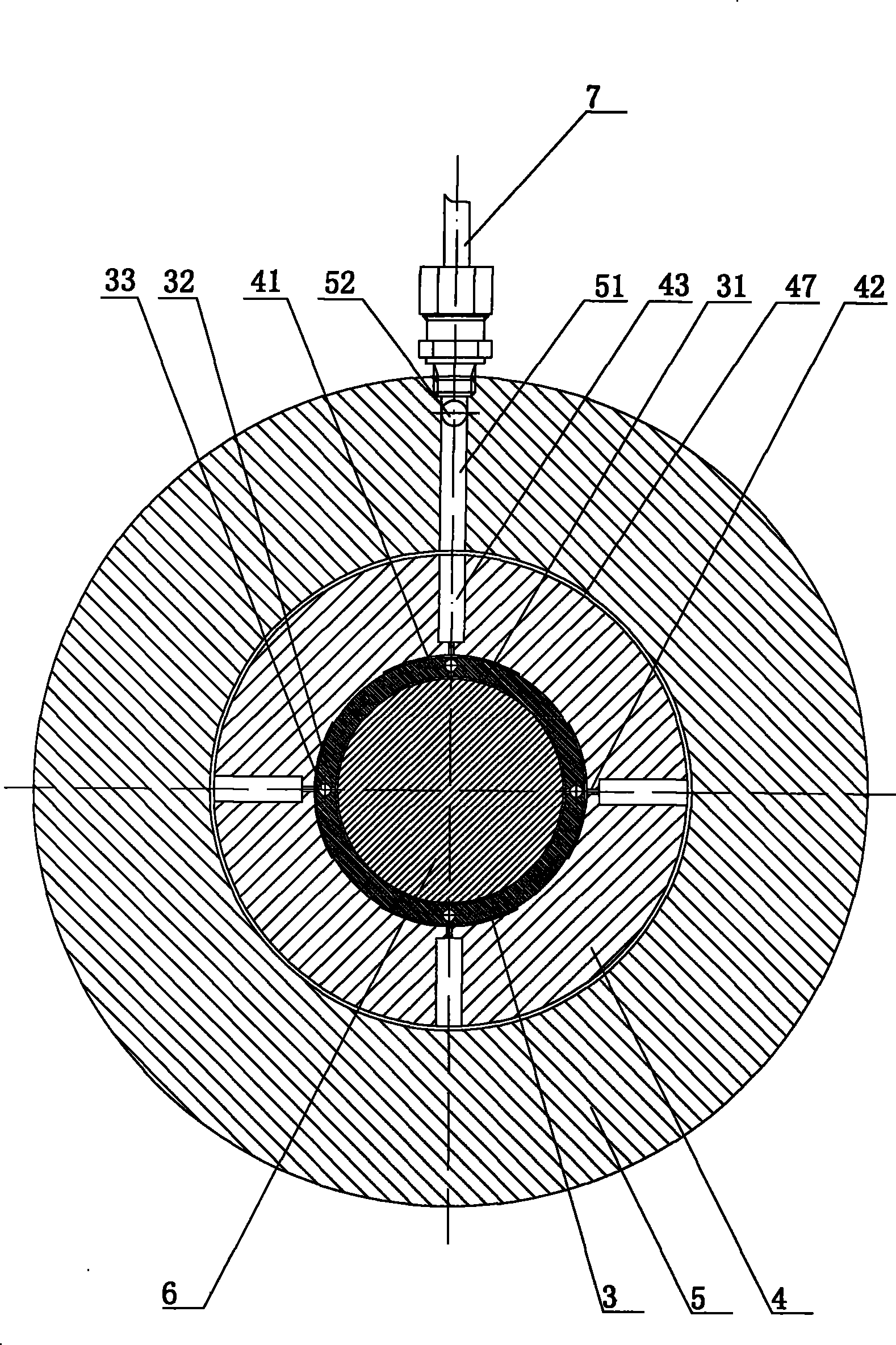
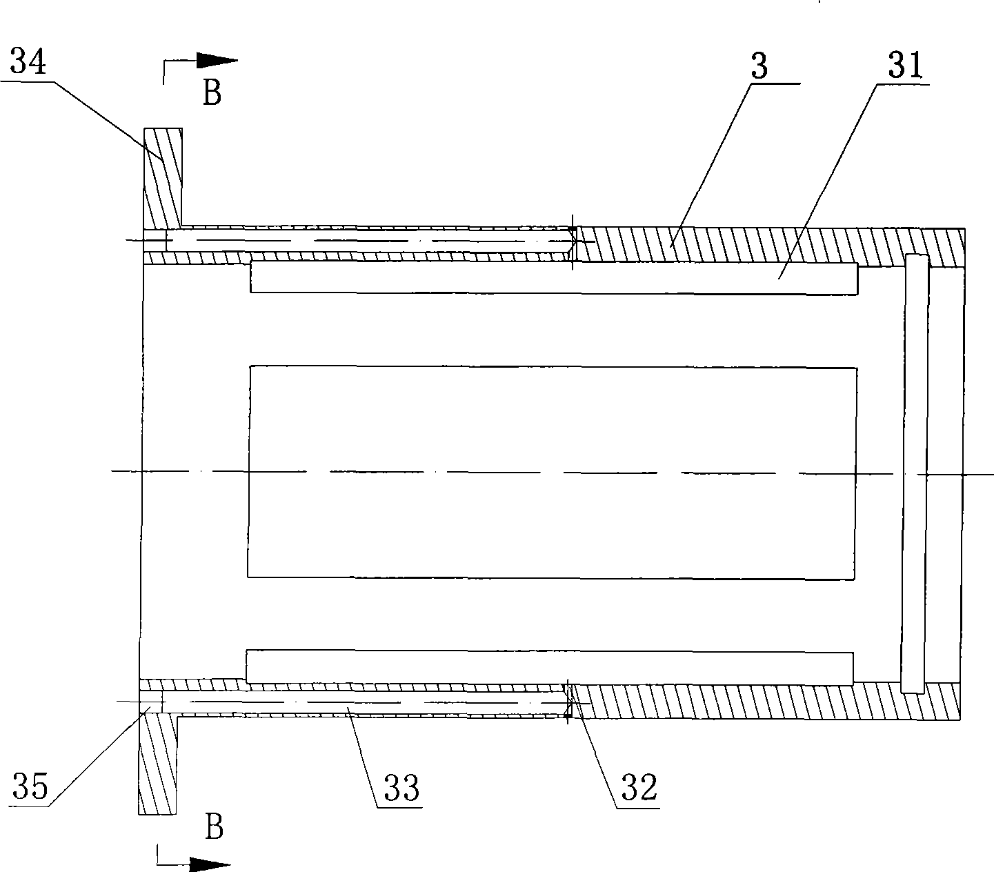
[0034] Such as Figure 1 to Figure 4 As shown, the independent oil supply structure of the inner and outer oil chambers of the floating ring bearing of the high-speed machine tool spindle of the present invention is provided with a bearing oil chamber 41 on the inner wall of the bearing 4 sleeved in the bearing seat 5, as a part of the entire floating ring bearing system The outer oil chamber is provided with a floating ring oil chamber 31 on the inner wall of the floating ring 3 sleeved in the bearing 4, as the inner oil chamber of the entire floating ring bearing system, the main shaft 6 is sleeved in the floating ring 3, and the bearing housing 5 End cover 1 and gasket 2 are installed at the end of the floating ring 3. The gasket 2 is sleeved on the thrust ring 34 of the floating ring 3, and is located between the end cover 1 and the bearing seat 5. The gap between the two sides of the thrust ring 34 It can be adjusted by the thickness of the gasket 2. At the same time, the...


PUM


Abstract

The invention discloses an independent oil supply structure of an inner oil cavity and an outer oil cavity of a floating ring bearing of a mainshaft of a high-speed machine tool. A bearing oil cavity is arranged on the inner wall of a bearing sleeved in a bearing seat and is used as the outer oil cavity of the whole floating ring bearing system; a floating ring oil cavity is arranged on the innerwall of a floating ring sleeved in the bearing and is used as the inner oil cavity of the whole floating ring bearing system; the structure is also provided with an oil supply circuit of the bearing oil cavity and an oil supply circuit of the floating ring oil cavity; the oil supply circuit of the bearing oil cavity is communicated with the bearing oil cavity through the bearing seat and the bearing sequentially; the oil supply circuit of the floating ring oil cavity is communicated with the floating ring oil cavity through the bearing seat, a cushion and an end cover arranged on the end partof the bearing seat, the floating ring subsequently; and two ends of the bearing oil cavity are provided with end release ring grooves. The independent oil supply structure of the inner oil cavity and the outer oil cavity of the floating ring bearing of the mainshaft of the high-speed machine tool has the advantages of avoiding high-temperature oil in the oil cavity of the inner wall of the bearing from entering the floating ring oil cavity and fully exerting high-speed performance of the floating ring bearing.

Description

technical field [0001] The invention relates to the field of mechanical manufacturing, in particular to an independent oil supply structure for the inner and outer oil chambers of the floating ring bearing of the main shaft of a high-speed machine tool. Background technique [0002] High-speed precision machining, characterized by high cutting speed, high feed speed, and high machining accuracy, is one of the four contemporary advanced manufacturing technologies, and a high-tech that makes the second revolutionary leap in manufacturing technology after numerical control technology. . High-speed precision machining machine tools not only have extremely high production efficiency, but also can significantly improve the machining accuracy and surface quality of parts. As the core functional component of the high-speed precision machine tool spindle, its performance directly affects the overall development level of the high-speed precision machining machine tool, and the bearin...

Claims


Application Information

Patent Timeline
Patent Type & Authority Patents(China)
IPC IPC(8): B23Q11/12
Inventor 熊万里纪宗辉冯春亚阳雪兵袁巨龙
Owner 吴寿麟
Learn More