Structure of instrument panel area of vehicle
A technology for automobile instrument panel and instrument panel, which is applied in the direction of instrument panel, vehicle components, vehicle safety arrangement, etc., can solve the problems of abutting the steering column cover and the instrument unit, and insufficient push-up.
- Summary
- Abstract
- Description
- Claims
- Application Information
AI Technical Summary
Problems solved by technology
Method used
Image
Examples
no. 1 example
[0045] Next, the structure around the instrument panel of an automobile according to the first embodiment of the present invention will be described.
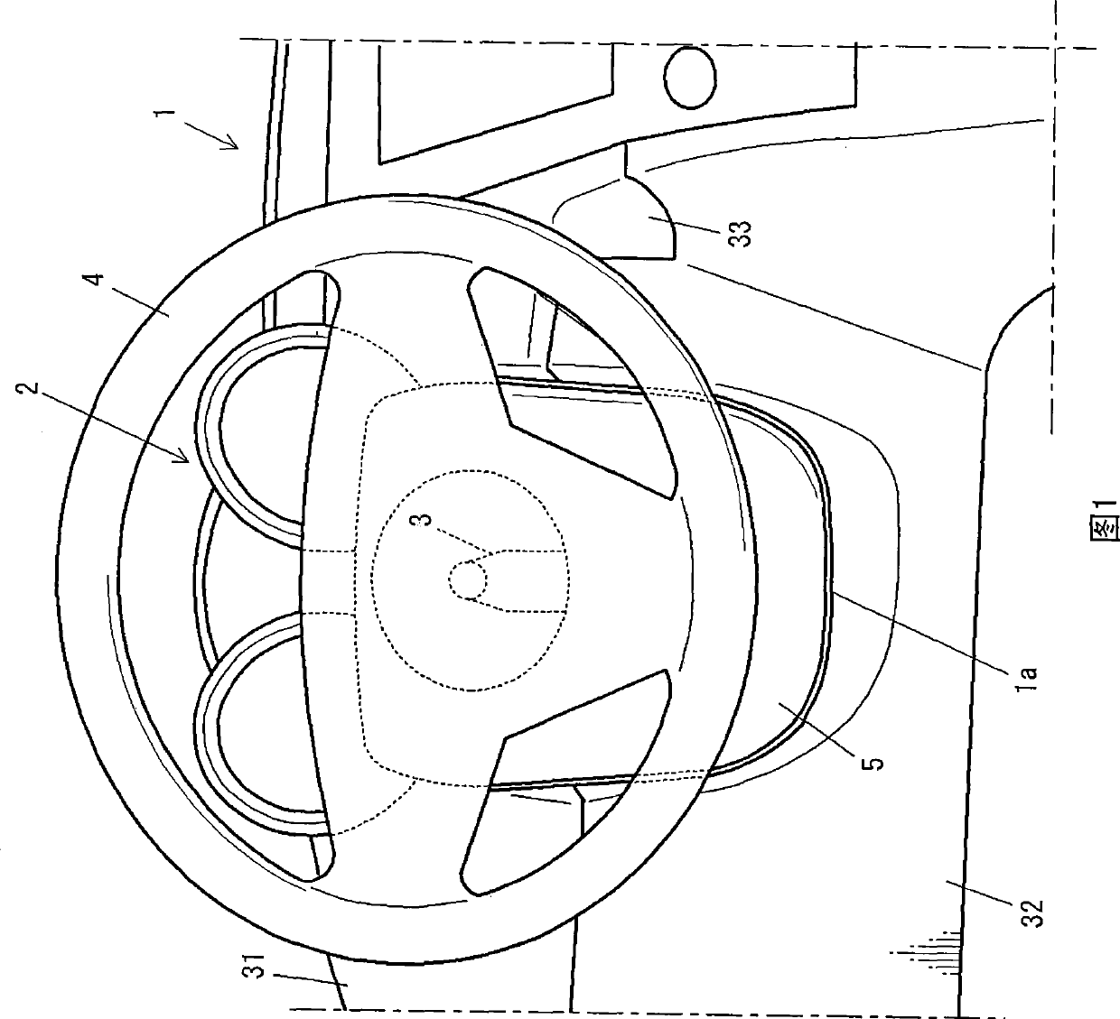
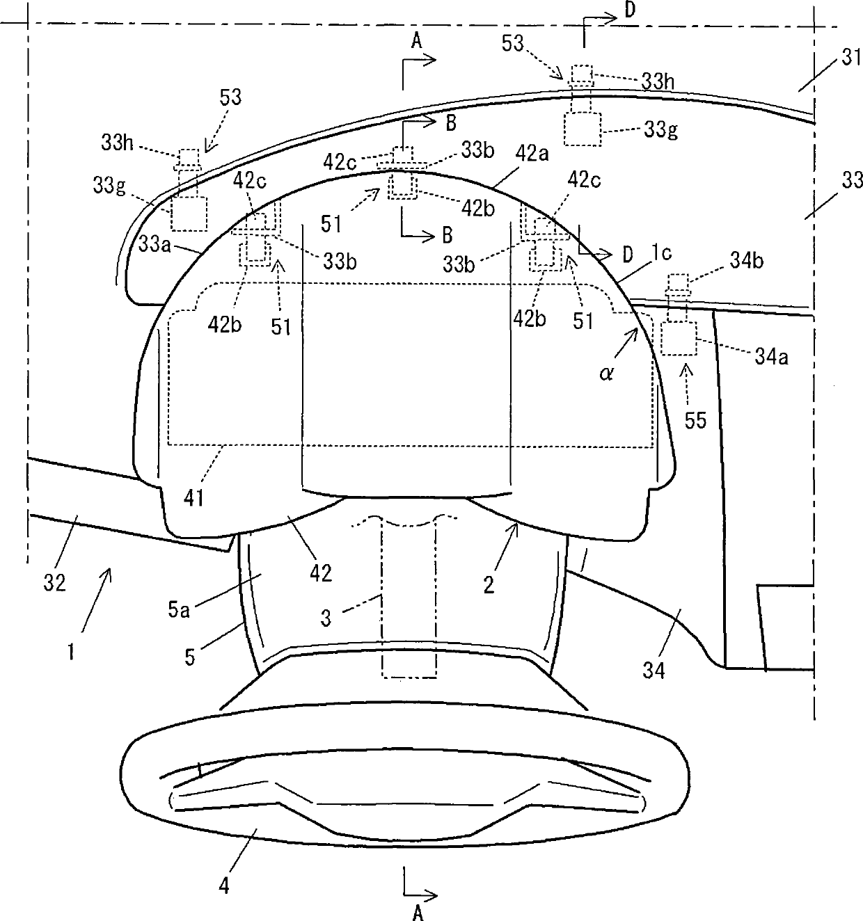
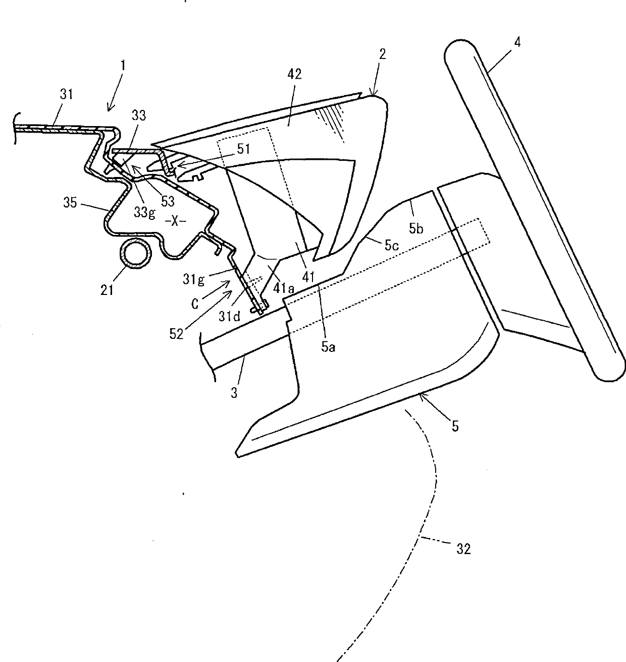
[0046] figure 1 It is a front view of the front part of the driver's seat in the automobile instrument panel involved in this embodiment, figure 2 is a top view of the front portion, image 3 is along figure 2 A cross-sectional view of line A-A in . In addition, although the example is an automobile with a left-hand steering wheel, it can also be applied to a car with a right-hand steering wheel.
[0047] Such as Figure 1 ~ Figure 3 As shown, in the instrument panel 1, an instrument unit 2 is provided in front of the driver's seat. In addition, a steering column 3 extends through the instrument panel 1 toward the rear of the vehicle, and a steering wheel 4 is attached to the end portion on the vehicle inner side. Furthermore, a steering column cover 5 is attached to a portion of the steering column 3 rearward of the in...
no. 2 example
[0090] Next, a structure around an automobile dashboard according to a second embodiment of the present invention will be described.
[0091] Here, in the second embodiment, also in the same manner as in the first embodiment, the steering column cover 5 is viewed from the front view of the vehicle (the steering column 3 moves forward substantially horizontally, so it is roughly same) overlaps the meter unit 2 , and as a result, the cover 5 abuts against the meter unit 2 when it moves toward the front of the vehicle. Therefore, in the present embodiment, the instrument unit 2 is pushed up by deformation of the knee pad 60 for absorbing the impact applied to the occupant, thereby reducing the abutment of the instrument unit 2 and the steering column cover 5, so that the steering mechanism 10 can be moved toward the steering column cover 5. Move forward.
[0092] The knee pads 60 as Figure 12 , Figure 13 As shown, there is a load receiving portion 60a located below the left ...
PUM
 Abstract
Description
Claims
Application Information
 - R&D
- Intellectual Property
- Life Sciences
- Materials
- Tech Scout
- Unparalleled Data Quality
- Higher Quality Content
- 60% Fewer Hallucinations
Browse by: Latest US Patents, China's latest patents, Technical Efficacy Thesaurus, Application Domain, Technology Topic, Popular Technical Reports.
© 2025 PatSnap. All rights reserved.Legal|Privacy policy|Modern Slavery Act Transparency Statement|Sitemap|About US| Contact US: help@patsnap.com


