Method for sound field separation by pressure velocity method

A separation method and field separation technology, applied in the direction of measuring propagation velocity, measuring ultrasonic/sonic wave/infrasonic wave, measuring device, etc., can solve the problems of large separation error, measurement surface shape limitation, error, etc.

Inactive Publication Date: 2009-04-08
HEFEI UNIV OF TECH
View PDF0 Cites 25 Cited by
  • Summary
  • Abstract
  • Description
  • Claims
  • Application Information

AI Technical Summary

Problems solved by technology

The sound field separation method based on the spatial FFT method has its inherent defects: on the one hand, the shape of the measurement surface is limited, that is, it can only be a regular shape such as a plane, cylinder or sphere; on the other hand, it is affected by the FFT algorithm. The separation error is large, especially when the sound pressure difference from both sides of the measurement surface is large, the error is particularly obvious
Defects of this method: there are restrictions on the shape of the measurement surface, that is, it can only be a regular shape such as a plane, a cylinder or a sphere
Defects of this method: there are singular integrals, non-uniqueness of solutions, etc., and the calculation efficiency is low

Method used


Image

  • Method for sound field separation by pressure velocity method
  • Method for sound field separation by pressure velocity method
  • Method for sound field separation by pressure velocity method

Examples


Embodiment Construction

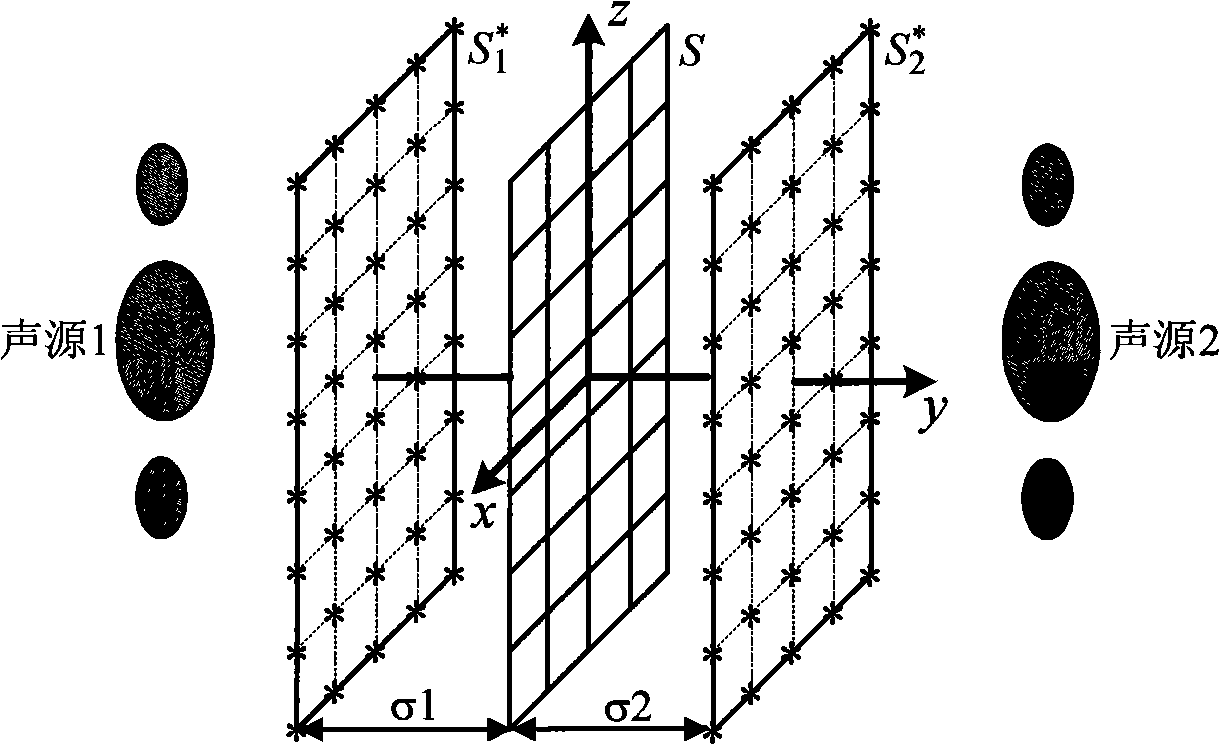
[0099] see figure 2 , in this embodiment, sound sources are distributed on both sides of the measurement surface, wherein sound source 1 is the main sound source, and sound source 2 is a noise source or a reflection or scattering source. In the measured sound field composed of sound source 1 and sound source 2 Among them, there is a measurement surface S located between the sound source 1 and the sound source 2; measurement grid points are respectively distributed on the measurement surface, and the distance between adjacent grid points is less than half a wavelength.

[0100] The specific implementation steps are:

[0101] a. Use single or multiple microphones and particle velocity sensors to scan the measurement surface separately, use a sound intensity probe array to take a snapshot of the measurement surface, or use a single or multiple sound intensity probe arrays to scan the measurement surface to obtain the measurement surface S sound pressure and particle velocity in...


PUM


Abstract

The invention discloses a pressure speed method sound field separation method, a measured sound field is provided with a measuring surface S; a sound pressure sensor is adopted to measure the sound pressure on the measuring surface S, and a particle velocity sensor or a sound intensity probe is adopted to measure the particle speed on the measuring surface S; both sides of the measuring surface S are provided with the imaginary source surfaces S1 <*> and S2 <*> which are provided with the equivalent sources; the transfer relationship between the equivalent sources and the sound pressure and the particle speed on the measuring surface S is constructed; the separation of sound source radiation sound pressure and the particle speed of both sides on the measuring surface according to the transfer relationship is realized; the sound field separation is realized by measuring the speed relation of sound pressure and particle on each surface; and the equivalent source method is adopted as the sound field separation arithmetic, the calculation stability is good, the calculation precision is high, and the implement is simple. The method can be widely applicable to the near-field acoustic holography measurement in the environments of internal sound field or noisy sound, the sound intensity method sound source identification in the noisy environment, the material reflection coefficient measurement, and the separation of the scattering sound field.

Description

Technical field: [0001] The invention relates to a sound field separation method in the field of noise in the physics profession, in particular to a pressure velocity method sound field separation method. Background technique: [0002] In actual measurement, it is usually encountered that there are sound sources on both sides of the measurement surface, or there is reflection or scattering on one side of the measurement surface. In actual engineering, in order to more accurately study the sound radiation characteristics of the actual sound source or the reflection characteristics of the reflective surface, it is necessary to separate the radiated sound from both sides of the measurement surface. In 1980, G.Weinreich et al proposed to use two methods of measuring very close to the measuring surface to realize the separation of incident wave and radiation wave. Based on the near-field acoustic holography technology proposed by E.G.Williams et al. and the double-surface measur...

Claims


Application Information

Patent Timeline
Patent Type & Authority Applications(China)
IPC IPC(8): G01H5/00G01H17/00
Inventor 毕传兴
Owner HEFEI UNIV OF TECH
Why Eureka
Try Eureka