Heat radiating device of air-guide duct

A technology of heat dissipation device and air duct, which is applied in cooling/ventilation/heating transformation, instrumentation, computing, etc., and can solve problems such as insufficient heat dissipation, low heat dissipation efficiency, and short circuit of the motherboard

Inactive Publication Date: 2011-06-15
LITE ON OPTO TECH (CHANGZHOU) CO LTD +2
View PDF0 Cites 0 Cited by
  • Summary
  • Abstract
  • Description
  • Claims
  • Application Information

AI Technical Summary

Problems solved by technology

As we all know, the screw structure is not easy to disassemble and assemble, and the cost is high. For example, skilled workers in Europe and the United States are charged for disassembling and disassembling screws, and it may also lead to the danger of missing screws and causing a short circuit on the motherboard.
In addition, the traditional air duct heat dissipation device is mainly made of plastic material, which is small in size, so the heat dissipation efficiency is low. In particular, only one fan is installed at one end, which cannot meet the high requirements of computer system heat dissipation.
For example, in order to solve the problem of poor heat dissipation caused by the closed high temperature of the computer mainframe placed in the automatic teller machine, a high-efficiency heat dissipation device is usually required

Method used


Image

  • Heat radiating device of air-guide duct
  • Heat radiating device of air-guide duct
  • Heat radiating device of air-guide duct

Examples


Embodiment Construction

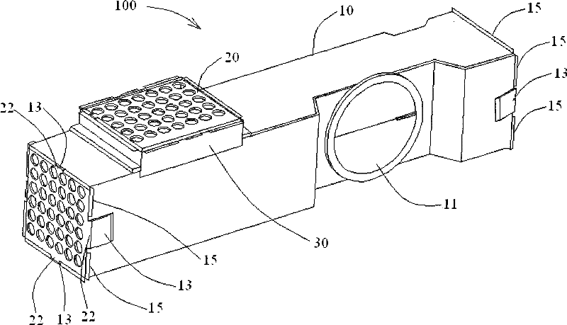
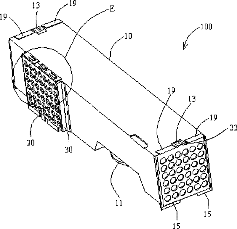
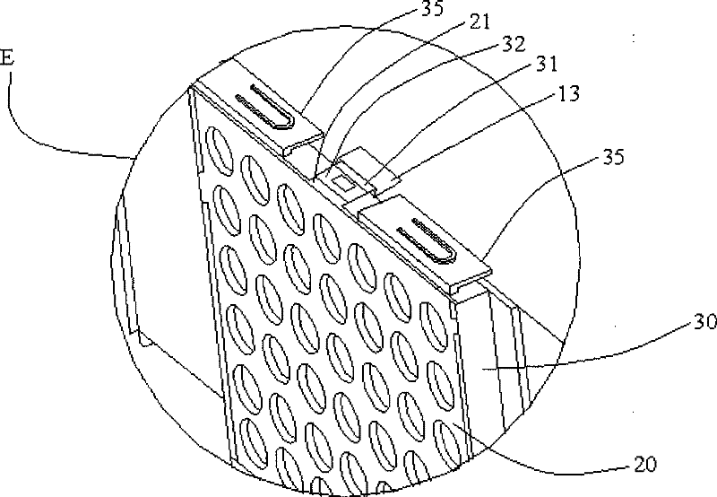
[0022] The structure of the air duct cooling device 100 provided by the present invention and its application in a computer system will be described below with reference to figures.

[0023] Please refer to figure 1 , figure 2 as well as image 3 , The air duct cooling device 100 includes an air duct 10 , and the air duct 10 is made of sheet metal parts and is roughly rectangular. The air duct 10 has an inlet 11 and three outlets, and each outlet is provided with a fan, wherein the fan is arranged on the inner side of the fan cover 20 in the figure.

[0024] Wherein, the inlet 11 is disposed on a first side of the air duct 10 , and in order to cooperate with the CPU to be dissipated and the cooling fins on the CPU, the surrounding structure of the inlet 11 is slightly recessed on the side. The outlets are respectively provided at both ends of the air duct 10 and a second side (ie, the end or side with the fan cover 20 ), wherein the second side is adjacent to the first sid...


PUM


Abstract

The invention relates to a guide duct heat abstractor which is applied in the computer system. The guide duct heat abstractor comprises a guide duct and at least one fan; wherein, the guide duct consists of sheet metal components and comprises an inlet and at least one outlet; the fan is fixed at the outlet by virtue of a block structure. The guide duct consists of the sheet metal components, so that the heat dissipation effect of the metal material is good; besides, the volume of the guide duct is larger, the two ends or the sides of the guide duct are provided with outlets and a plurality of fans are arranged, therefore, the heat dissipation efficiency is improved. In addition, the fans is fixed at the outlet of the guide duct by virtue of the block structure, so as to form a modular heat abstractor without using screws, therefore, the disassembly is convenient, the cost is saved, and the danger caused by short circuit of a motherboard due to the loss of the screws is avoided.

Description

technical field [0001] The invention relates to a heat dissipation device for an air duct, in particular to the heat dissipation device for an air duct used in a closed environment to dissipate heat for a computer system. Background technique [0002] With the improvement of the computer's main computing speed, the heat generated by the corresponding central processing unit (CPU) is also increasing. In order to make the CPU operate at a normal operating temperature, a radiator is usually provided for the CPU. Generally, the radiator includes cooling fins and a fan, wherein the cooling fins increase the heat dissipation area, and the fan enhances air convection, which is beneficial to take away heat. In order to transmit heat to a space away from the CPU, an air duct is usually added to reduce the temperature of the environment around the CPU more effectively and facilitate heat dissipation. [0003] Generally, the traditional computer mainframe air duct is mainly made of pl...

Claims


Application Information

Patent Timeline
Patent Type & Authority Patents(China)
IPC IPC(8): G06F1/20H05K7/20
Inventor 冒淑华
Owner LITE ON OPTO TECH (CHANGZHOU) CO LTD
Why Eureka
Try Eureka