Vibration energy collector with piezomagnetic/piezoelectric composite energy conversion structure

A technology of vibration energy harvesting and magnetoelectric transducers, applied in generators/motors, piezoelectric effect/electrostrictive or magnetostrictive motors, piezoelectric/electrostrictive/magnetostrictive devices, etc., can Solve the problems of high battery cost, obstacles to power supply, inability to use wired power supply, etc., and achieve high magnetoelectric conversion efficiency

Inactive Publication Date: 2009-04-08
CHONGQING UNIV
View PDF16 Cites 23 Cited by
  • Summary
  • Abstract
  • Description
  • Claims
  • Application Information

AI Technical Summary

Problems solved by technology

However, whether it is wireless sensing products or micro-electromechanical devices, the problem of power supply is becoming a big obstacle to their development
The reason is that the current means of powering these systems mainly rely on bat

Method used


Image

  • Vibration energy collector with piezomagnetic/piezoelectric composite energy conversion structure
  • Vibration energy collector with piezomagnetic/piezoelectric composite energy conversion structure
  • Vibration energy collector with piezomagnetic/piezoelectric composite energy conversion structure

Examples


Embodiment 1

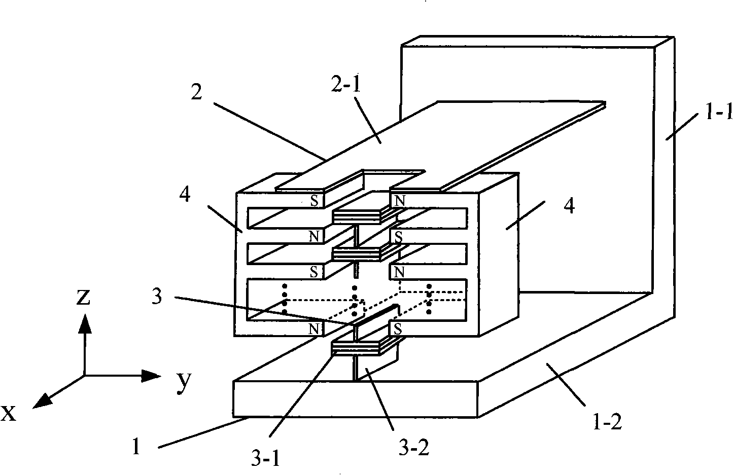
[0031] See attached figure 1 , as shown in the figure, the devices used in this example include: "L"-shaped support mechanism 1, plate-shaped elastic cantilever beam 2-1, block-shaped laminated transducing structure 3-1 and plate-shaped rib 3-2 Composed of piezoelectric / piezoelectric composite magnetoelectric transducer 3, two symmetrical interdigitated permanent magnet magnetic circuits 4, the interdigitated fingers are placed opposite each other, and the upper ends of the two interdigitated permanent magnet magnetic circuits 4 are fixed on the elastic One end of the lower side of the cantilever beam 2-1, and the other end of the elastic cantilever beam 2-1 are fixed on the support 1-1 of the "L"-shaped support mechanism 1, and the piezoelectric / piezoelectric composite magnetoelectric transducer 3 passes through the rib plate 3-2 is connected and fixed on the base 1-2 of the "L"-shaped support mechanism 1 through the rib plate 3-2, and the piezoelectric / piezoelectric composit...

example 2

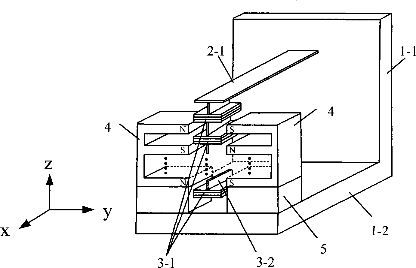
[0037] See attached figure 2 , it differs from Embodiment 1 in that: the introduction of non-magnetic material 5 is used to connect the lower ends of the two interdigitated permanent magnet magnetic circuits 4 with the base 1-2; what is fixedly connected with the elastic cantilever beam 2-1 is a pressure The magnetic / piezoelectric composite magnetoelectric transducer 3, the upper end of the rib plate 3-2 of the piezoelectric / piezoelectric composite magnetoelectric transducer 3 is fixed on one side of the lower side of the elastic cantilever beam 2-1.

[0038] When the elastic cantilever beam 2-1 drives the laminated transduction structure 3-1 and the permanent magnet magnetic circuit 4 to produce reciprocating relative motion, the piezomagnetic layer in the laminated transduction structure 3-1 enters regions with different magnetic induction intensities, The y-axis in the chemicalization direction produces stretching deformation, and this mechanical motion is transmitted to t...

Embodiment 3

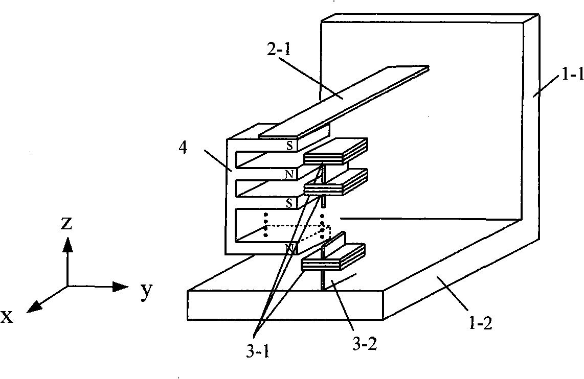
[0040] See attached image 3 , the structure of this example is different from Embodiment 1 in that: the two interdigitated permanent magnet magnetic circuits 4 are replaced by a single interdigitated permanent magnet magnetic circuit 4; when excited by external vibration, the elastic cantilever beam 2- 1 drives the unilateral interdigitated permanent magnet magnetic circuit 4 to reciprocate, and the principle of electromechanical conversion is the same as that of embodiment 1.


PUM


Abstract

The invention discloses a vibrational energy collecting device adopting a piezomagnetic/piezoelectric compound transduction structure. The device comprises a supporting mechanism, a piezomagnetic/piezoelectric compound magneto-electricity transducer, a permanent magnet magnetic circuit and an elastic mechanism; wherein, the piezomagnetic/piezoelectric compound magneto-electricity transducer is arranged in the space of the air gap field of the permanent magnet magnetic circuit; one of the piezomagnetic/piezoelectric compound magneto-electricity transducer and the permanent magnet magnetic circuit is elastically connected with the supporting mechanism by the elastic mechanism and can do reciprocating movement along with the mechanism while the other is fixed on the base of the supporting mechanism; namely, the piezomagnetic/piezoelectric compound magneto-electricity transducer is fixed on the base while the permanent magnet magnetic circuit is connected with the supporting mechanism by the elastic mechanism, or the piezomagnetic/piezoelectric compound magneto-electricity transducer is connected with the supporting mechanism by the elastic mechanism while the permanent magnet magnetic circuit is fixed on the base by non-permeability magnetic material. The invention has the beneficial effect that the invention provides a self-energized device which is applicable to weak vibration and has higher magnetoelectricity conversion efficiency.

Description

technical field [0001] The invention relates to a technology capable of converting mechanical vibration energy into electric energy and collecting it, in particular to a vibration energy collector adopting a piezoelectric / piezoelectric composite energy conversion structure. Background technique [0002] Electronic products continue to develop in the direction of miniaturization. The development of Bluetooth technology and low-power communication standards (such as Zigbee and IEEE802.15.4) has largely promoted the research of wireless sensor networks and communication nodes. Due to the energy The characteristics of low power consumption, small size, large function, and mass production are also developing rapidly. However, whether it is wireless sensing products or micro-electromechanical devices, the problem of power supply is becoming a great obstacle to their development. The reason is that the current means of powering these systems mainly rely on batteries or power lines...

Claims


Application Information

Patent Timeline
IPC IPC(8): H02N2/18H01L41/113H01L41/12
Inventor 文玉梅杨进李平代显智
Owner CHONGQING UNIV
Why Eureka
Try Eureka