
Heating device using an exhausted engine heat

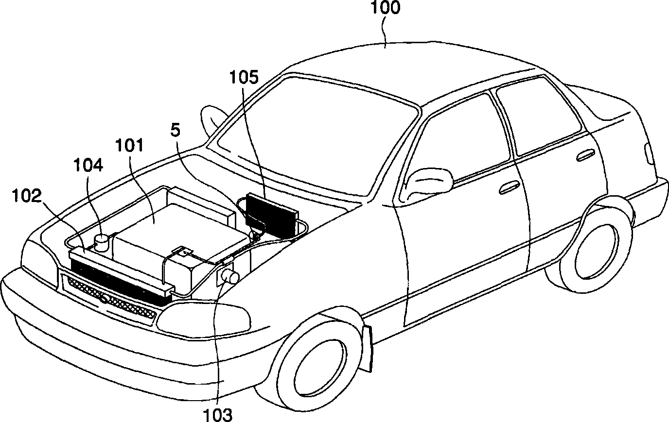
一种加热装置、发动机的技术,应用在加热/冷却设备、换热器、换热器类型等方向,能够解决安装和维护困难、驾驶员不方便、冷却液不足以加热车辆内部等问题,达到提高效率、方便维护的效果

Inactive Publication Date: 2010-11-03
DASAN
View PDF4 Cites 0 Cited by
  • Summary
  • Abstract
  • Description
  • Claims
  • Application Information

AI Technical Summary

Problems solved by technology

However, this conventional heating device has a problem that the control valve is installed in the engine compartment and is manually operated, so whenever the control valve is operated, the engine compartment must be opened, which is inconvenient for the driver
Another problem with conventional heating units is that the amount of coolant provided is not sufficient to heat the interior of the vehicle
In addition, if the heating device is installed in the engine compartment, additional pipes must be installed, so the structure is very complicated and difficult to install and maintain

Method used


Image

  • Heating device using an exhausted engine heat
  • Heating device using an exhausted engine heat
  • Heating device using an exhausted engine heat

Examples


Embodiment Construction

[0062] Preferred embodiments of the present invention will be described in detail below with reference to the accompanying drawings.

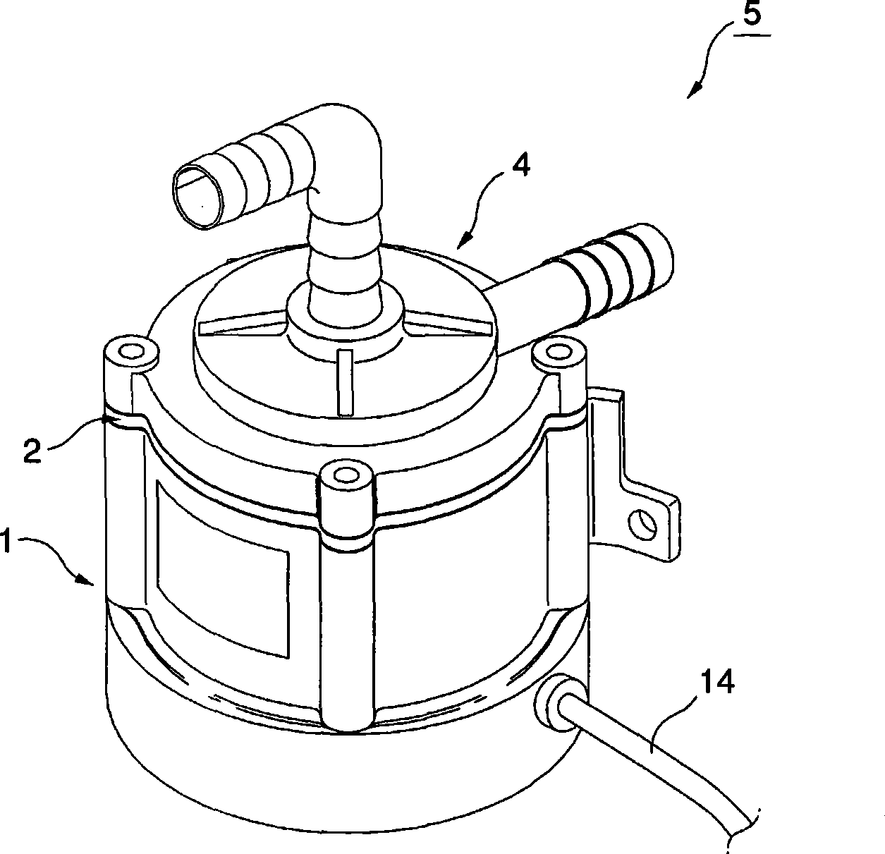
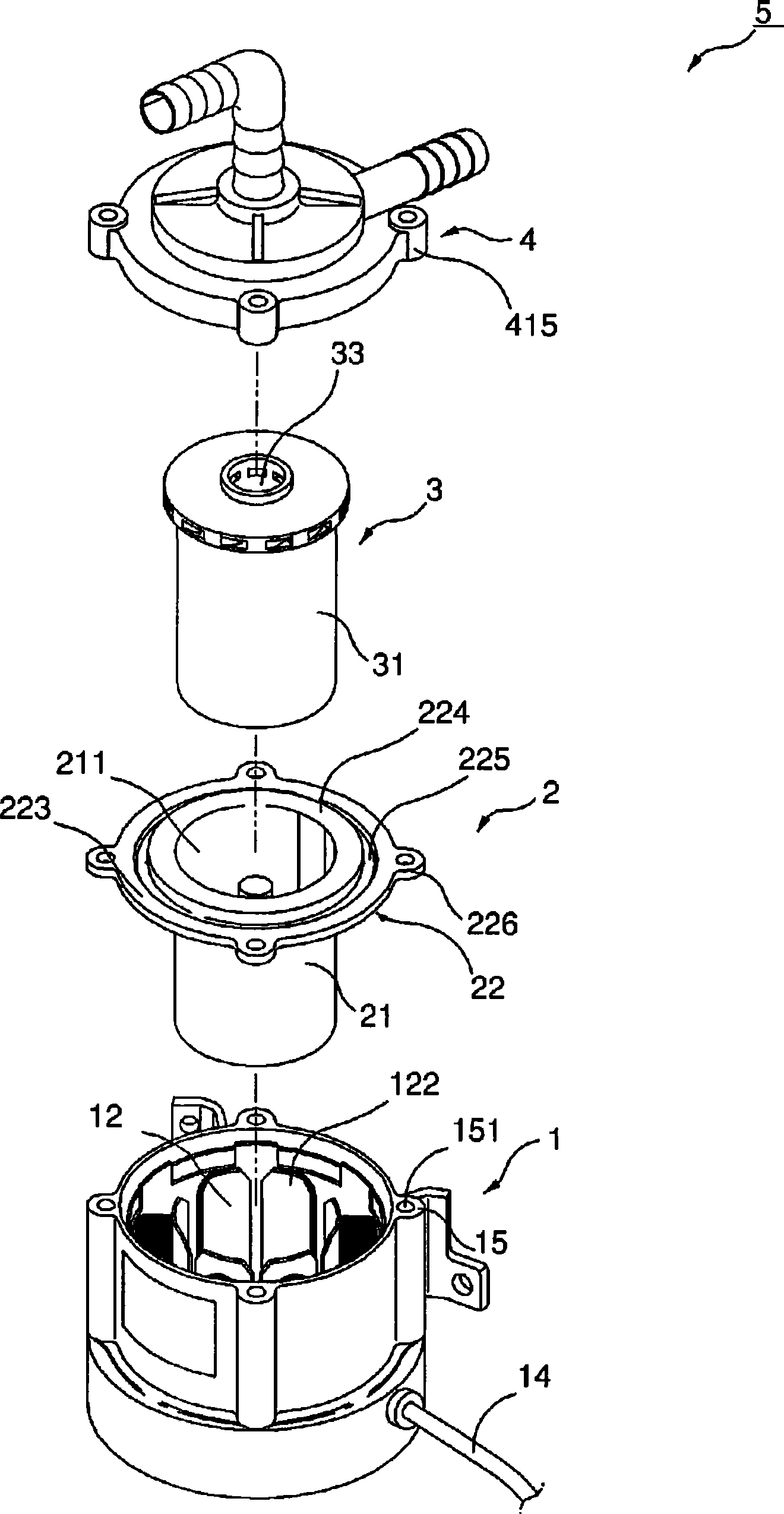
[0063] figure 2 is a perspective view of a heating device in a preferred embodiment of the present invention, image 3 It is an exploded perspective view of the heating device in the preferred embodiment of the present invention.

[0064] From figure 2 and 3 It can be seen from the figure that the heating device 5 utilizing waste heat of the engine includes a main body 1 , a receiving part 2 , a rotor 3 and a cover 4 .

[0065] Figure 4 is a plan view of the main body in the preferred embodiment of the present invention.

[0066] From image 3 and 4 As can be seen in the figure, the main body 1 is open on one side and closed on the other. The main body is hollow cylindrical with preset radii R1 and R2. The main body includes a driving part 11 , a receiving part insertion cavity 12 , a control unit 13 , electric wires 14 and a first ...


PUM


Abstract

Disclosed herein is a heating device using waste engine heat. When an engine is stopped for a driver to rest in a vehicle or leave the vehicle for a meal, a manipulation switch in the vehicle is turned on to forcibly circulate coolant heated by engine heat, thus heating the interior of the vehicle. The device includes a main body which generates rotating force by current supplied from a vehicle battery, when an engine is stopped. A receiving part is received in the main body, and prevents coolant from flowing into the main body. A rotor is inserted into the receiving part, receives the coolant, and is rotated depending on a varying polarity, thus discharging the coolant. A lid introduces the coolant from the engine through one side, supplies the coolant to the rotor, and discharges the coolant to a heater coupled to the other side.

Description

technical field [0001] In general, the present invention relates to a device for heating the interior of a vehicle, and more particularly, to a heating device utilizing waste heat from an engine. The battery on the battery provides current. When the current is connected to the main body, it can generate rotational power. The receiving part installed on the main body prevents the coolant from flowing into the main body. The rotor inserted on the receiving part receives the cooling liquid. When the current is connected to the main body, the rotor relies on The polarity is changed to rotate, so as to discharge the coolant, guide the coolant of the engine through one side of the cover, provide coolant to the rotor, discharge the coolant, and the coolant has rotational power when passing through the rotor, and reaches the heating connected to the other side of the cover device. Background technique [0002] Generally speaking, vehicles are equipped with heating devices to keep t...

Claims


Application Information

Patent Timeline
Patent Type & Authority Patents(China)
IPC IPC(8): B60H1/00
CPCB60H1/03B60H1/04B60H1/00885F28D21/0001
Inventor 朴铉相
Owner DASAN
Learn More