Transmission unit for vehicles

A technology for transmissions and vehicles, applied in transmissions, differential transmissions, control devices, etc., can solve problems such as transmission damage and deterioration of meshing behavior.

Inactive Publication Date: 2009-04-08
AMER SPA
View PDF0 Cites 4 Cited by
  • Summary
  • Abstract
  • Description
  • Claims
  • Application Information

AI Technical Summary

Problems solved by technology

[0011] This necessarily worsens the meshing behavior between the crown wheel and the worm which itself transmits the motion to the crown wheel, with the result that the transmission suffers considerable damage over time

Method used


Image

  • Transmission unit for vehicles
  • Transmission unit for vehicles
  • Transmission unit for vehicles

Examples


Embodiment Construction

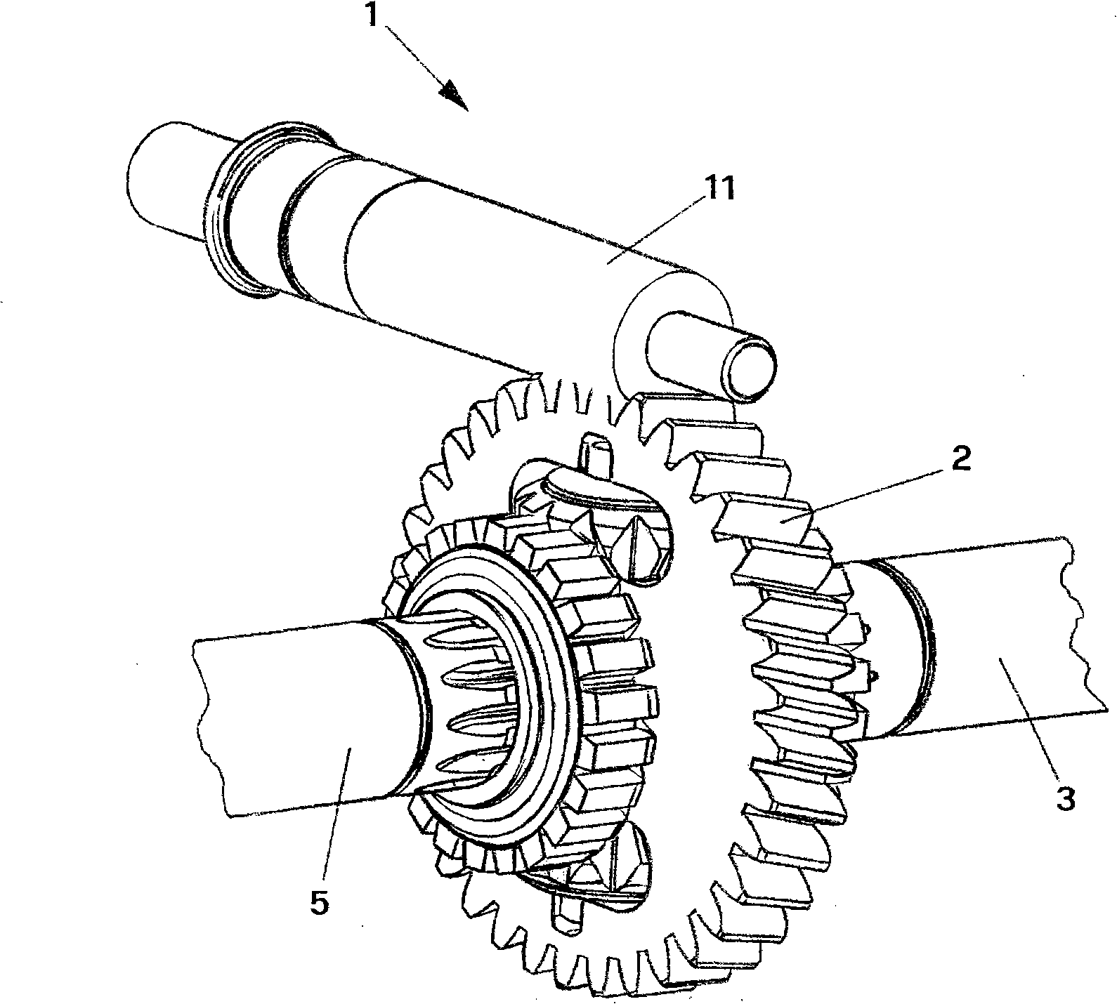
[0028] With reference to the above drawings in particular figure 1 , it can be seen that the transmission device of the present invention includes a drive shaft generally marked as 1, and a pinion 11 meshing with the crown gear 2 is arranged on the end of the drive shaft.

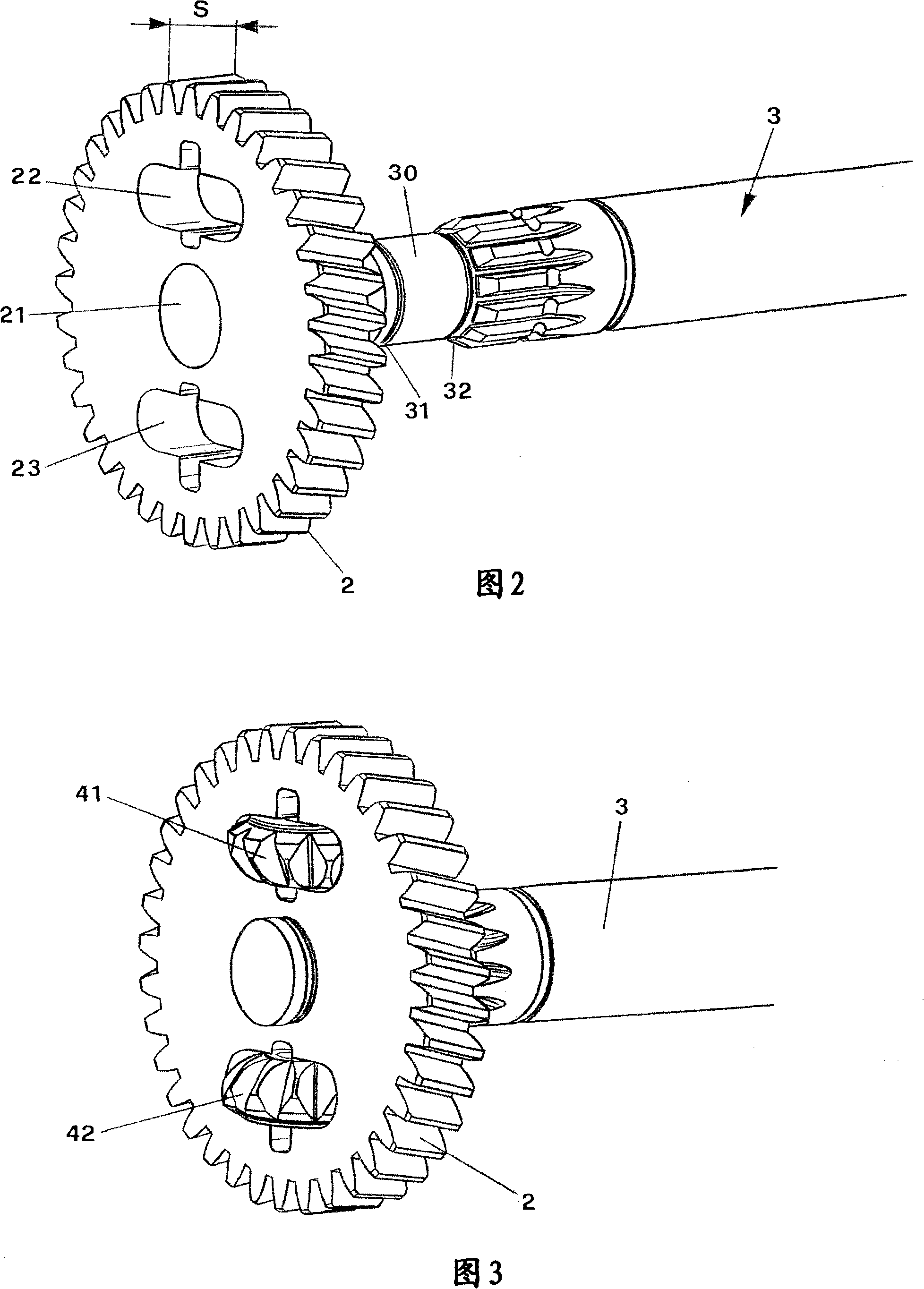
[0029] As shown in more detail in FIG. 2, the crown wheel has a central bore 21 adapted to receive a drive shaft and two identical and opposite cavities 22 and 23, which, as will be explained below, 23 accommodate the same number of planetary gears.

[0030] The crown wheel 2 is preferably made of copper in order to facilitate the machining of the gear teeth, the abutments 21 , 22 and 23 and also the meshing of the gear teeth with the pinion 11 of the drive shaft 1 .

[0031] The end 30 of one of the two driving shafts marked 3 is longer than the thickness S of the crown wheel 2 .

[0032] The diameter of said end 30 is substantially equal to the diameter of the bore 21 of the crown wheel, but with limite...


PUM


Abstract

The invention is a transmission unit with orthogonal axes for vehicles, comprising: a drive shaft (1) connected to a gearmotor unit with differential, comprising: a crown gear (2) that meshes with the drive shaft (1), said crown gear housing, in two diametrically opposed cavities (22, 23), one pair of planetary gear wheels (41, 42) having their axis lying on an ideal plane containing said crown gear; two sun gear wheels (35, 55) meshing with said planetary gear wheels (41, 42), each connected to an axle shaft (3, 5) belonging to a driven wheel. The crown gear is housed, rotatingly free, in one axle shaft (3) only.

Description

technical field [0001] The present invention relates to a transmission for use in vehicles, especially but not necessarily electric vehicles such as wheelchairs for disabled persons and floor washer / dryers. [0002] More specifically, the transmission that is the subject of the present invention refers to a differential gear motor arrangement and the constructional features of said arrangement. Background technique [0003] Differential gear motor arrangements commonly used today in different fields, especially in the field of electric transmission, consist of drive shafts connected to a differential; in the case of gear motors with orthogonal axes, said shafts are moved by worm-type passed to the crown gear. [0004] In some cases, the crown gear is provided with two diametrically opposed cavities housing planetary gears meshing with two sun gears, each of which is attached to a respective motor that transmits motion to the driven wheel. drive shaft. [0005] The crown g...

Claims


Application Information

Patent Timeline
Patent Type & Authority Applications(China)
IPC IPC(8): F16H48/08B60K17/16
CPCF16H2048/385F16H48/08F16H48/40
Inventor 弗郎切斯科·巴蒂斯泰拉
Owner AMER SPA
Why Eureka
Try Eureka