
Hydraulic cylinder-controlled oblique tray type plunger hydraulic transformer

A technology for hydraulic transformers and hydraulic cylinders, applied in the field of hydraulic components, can solve the problems of unfavorable system automatic flow and pressure accurate control, and the inability to realize displacement adjustment of electronically controlled quantitative hydraulic transformers, and achieve the effect of improving application performance.

Active Publication Date: 2009-04-15
山东严格产业发展有限公司
View PDF0 Cites 7 Cited by
  • Summary
  • Abstract
  • Description
  • Claims
  • Application Information

AI Technical Summary

Problems solved by technology

[0007] The purpose of the present invention is to provide a hydraulic cylinder control swash plate type plunger hydraulic transformer to solve the problem that the manual control hydraulic transformer is not conducive to the automation of the system and the precise control of flow and pressure, and the electric control quantitative hydraulic transformer cannot realize the displacement. Regulatory issues

Method used


Image

  • Hydraulic cylinder-controlled oblique tray type plunger hydraulic transformer
  • Hydraulic cylinder-controlled oblique tray type plunger hydraulic transformer
  • Hydraulic cylinder-controlled oblique tray type plunger hydraulic transformer

Examples


specific Embodiment approach 1

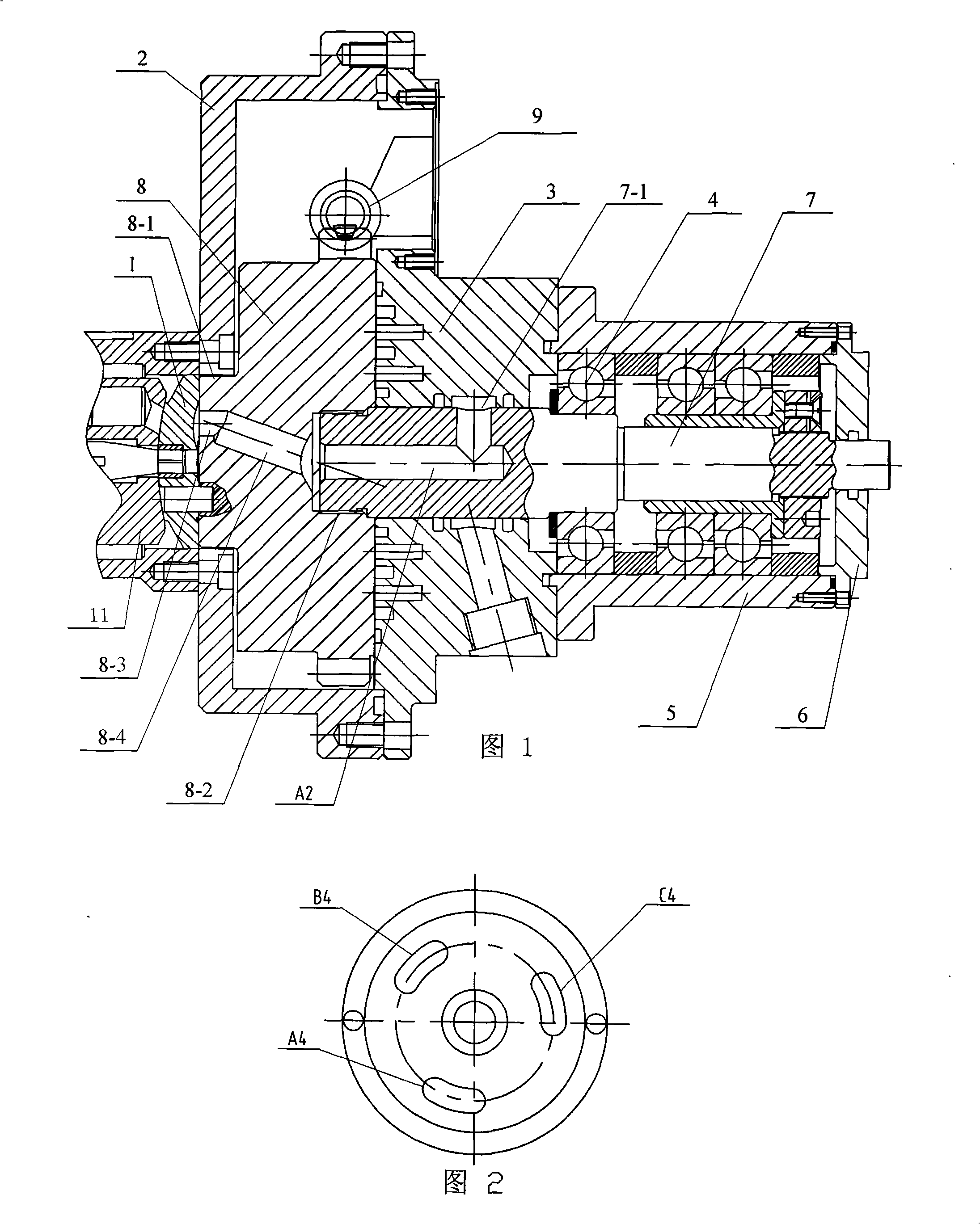
[0011] Specific Embodiment 1: This embodiment will be described with reference to FIGS. 1 to 10. The hydraulic transformer of this embodiment includes a front valve plate 1, a hydraulic transformer casing 2, an oil passage transition block 3, a bearing 4, a bearing seat 5, an end cover 6 and The main shaft 7; the hydraulic transformer also includes a rear distribution plate 8, a hydraulic cylinder 9 and a rack 10, the rear distribution plate 8 is installed in the hydraulic transformer shell 2, and the small-diameter end surface 8-1 of the rear distribution plate 8 is connected to the The front distribution plate 1 arranged on the outer side of the hydraulic transformer housing 2 is connected by pins, and the outer wall of the large-diameter end surface 8-5 side of the rear distribution plate 8 is processed with teeth along the circumferential direction. The hydraulic cylinder 9 is composed of a hydraulic cylinder body 9 -1 and two pistons 9-2, the rack 10 is installed in the hy...

specific Embodiment approach 2

[0012] Specific embodiment two: This embodiment is described in conjunction with Fig. 1, Fig. 8 and Fig. 9. The high-pressure oil hole A1 of the oil passage transition block 3 in this embodiment is a high-pressure oil hole inclined toward the direction of the rear distribution plate 8, and the oil passage Both the load oil hole B1 and the oil return tank oil hole C1 of the transition block 3 are L-shaped. Other components and connections are the same as those in the first embodiment.

specific Embodiment approach 3

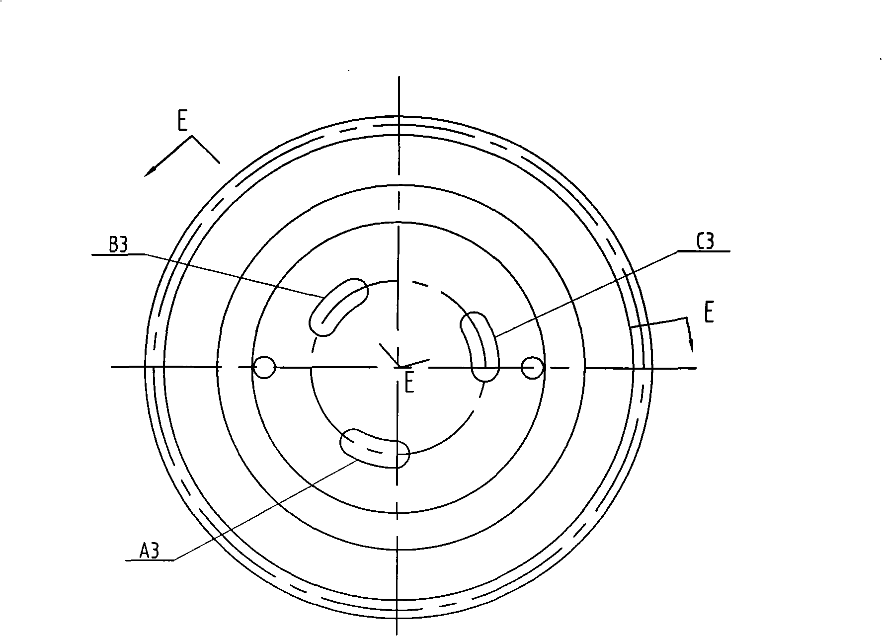
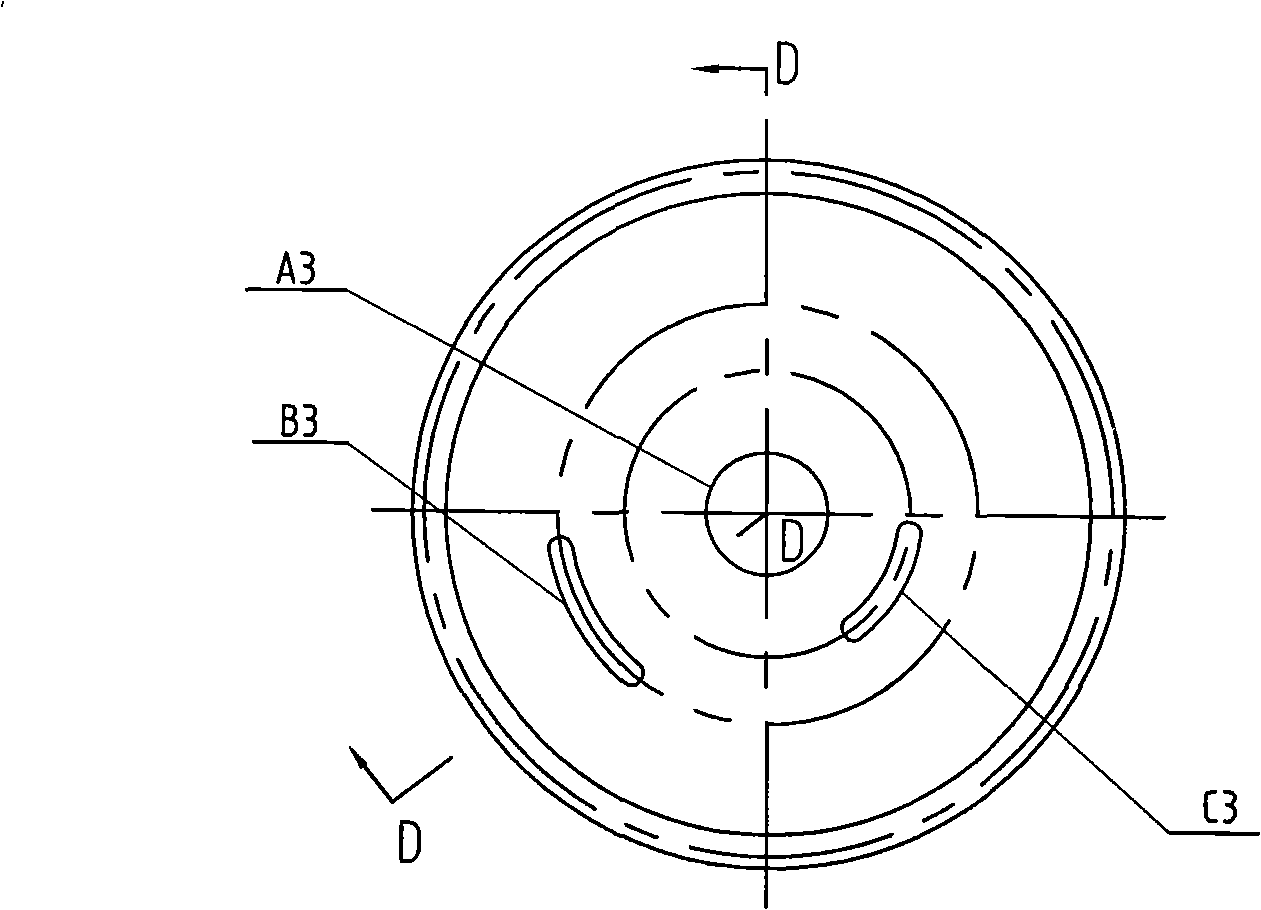
[0013] Specific implementation mode three: combination Figure 5 with Image 6 To illustrate this embodiment, the high-pressure passage A3, the load passage B3 and the oil return tank passage C3 on the rear distribution plate 8 of this embodiment are all composed of an axial straight passage 8-3 and an inclined passage 8-4, and the axial straight passage 8-3 is located on the small-diameter end face 8-1 of the rear distribution plate 8, which is convenient for outputting oil. Other components and connections are the same as those in the first embodiment.


PUM


Abstract

The invention discloses a hydraulic cylinder controlled swash plate type plunger hydraulic transformer and relates to a swash plate type piston hydraulic transformer, aiming at solving the problems that the manually controlled hydraulic transformer can not control the flow and the pressure accurately and the electricity-controlled quantitative type hydraulic transformer can not realize displacement regulation. A rear port plate is fixedly connected with a front port plate; the rear port plate is processed with a gear; a rack is arranged inside a hydraulic cylinder and is fixedly connected with a piston; the rack is meshed with the teeth on the rear port plate; a main axis penetrates the transition block of an oil circuit and then is fixedly arranged in the rear port plate; a high-pressure oil hole on the transition block of the oil circuit is communicated with a high pressure oil circuit on the front port plate by a high-pressure oil duct on the main axis and a high-pressure channel on the rear port plate; a load oil hole on the transition block of the oil circuit is communicated with a load oil circuit on the front port plate by a load channel on the rear port plate; and the oil hole of an oil sump tank on the transition block of the oil circuit is communicated with the oil circuit of the oil sump tank on the front port plate by the channel of the oil sump tank on the rear port plate. The hydraulic transformer can accurately control the flow and pressure and achieve displacement regulation.

Description

technical field [0001] The invention relates to a swash plate type plunger hydraulic transformer, which belongs to the technical field of hydraulic components. Background technique [0002] The hydraulic constant pressure network secondary regulation technology developed in recent years has improved the flexibility and efficiency of the hydraulic system. The principle of secondary regulation has many advantages. However, when driving a linear load, the traditional method is to achieve throttling control. Since there is a large pressure difference in throttling control, this control method brings a large energy loss. How to transmit the energy of the constant voltage network with variable pressure without energy loss like a power transformer or a mechanical gear transmission, this is the technical background of the hydraulic transformer. [0003] The traditional hydraulic transformer directly connects the hydraulic motor and the hydraulic pump coaxially. By adjusting the dis...

Claims


Application Information

Patent Timeline
IPC IPC(8): F04B1/12F04B1/26F15B21/00
Inventor 姜继海刘成强于安才孙毅
Owner 山东严格产业发展有限公司
Features
  • Generate Ideas
  • Intellectual Property
  • Life Sciences
  • Materials
  • Tech Scout
  • Unparalleled Data Quality
  • Higher Quality Content
  • 60% Fewer Hallucinations
Learn More