Wristwatch case

A shell and wristwatch technology, applied to clocks, shells, mechanically driven clocks, etc., can solve problems such as weak elasticity and limited cushioning effect

Inactive Publication Date: 2009-04-15
モントレワイラーソシエテアノニムジュネーブ
View PDF1 Cites 4 Cited by
  • Summary
  • Abstract
  • Description
  • Claims
  • Application Information

AI Technical Summary

Problems solved by technology

The elasticity of these resins is relatively weak, so the

Method used


Image

  • Wristwatch case
  • Wristwatch case
  • Wristwatch case

Examples


Embodiment Construction

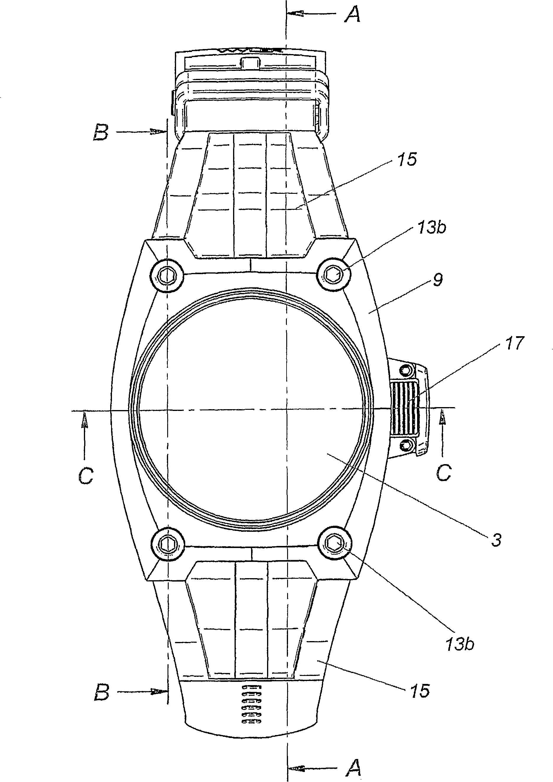
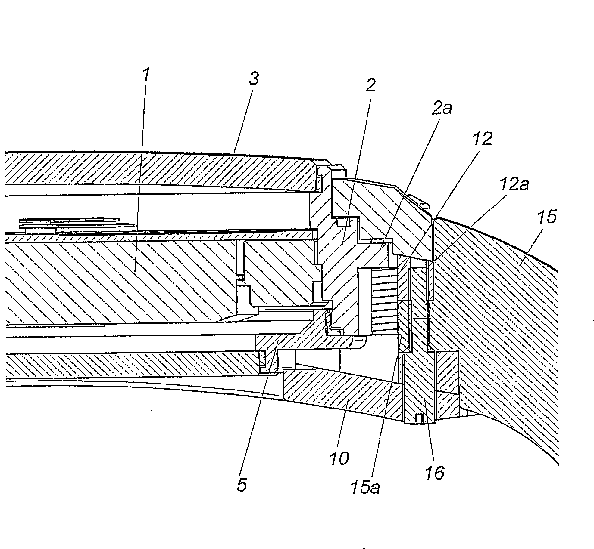
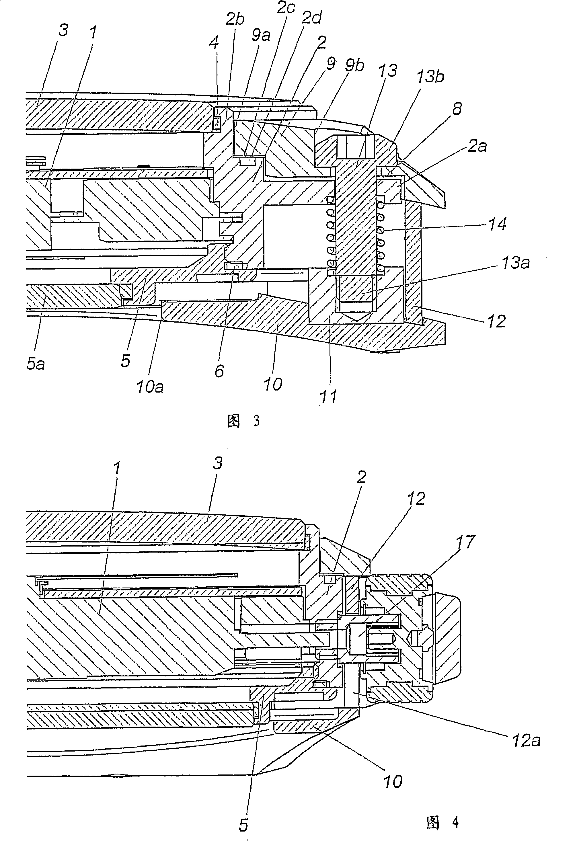
[0013] The case of the wrist watch according to the invention comprises a closure unit intended to house the movement of the watch 1 and which in this embodiment has a middle part 2 whose upper opening is covered by a pressed crystal with an insert seal 4 -in crystal) 3 closed, while its lower opening is closed by a threaded back (screwedback) 5 with a seal 6. In this embodiment, said back 5 is provided with a transparent central portion 5a in order to be able to see the movement. As with all watch cases, the unit consists of at least one control stem 17 ( figure 1 and Fig. 4) are preferably passed through watertightly. This closed unit thus forms the sealed protective case of movement 1 .

[0014] Said closed unit is mounted by means of an elastic suspension, which will be described below, in a sheath comprising a top member 9 with a central opening 9a through which the portion 2b of the middle piece 2 passes, The crystal cover 3 is fixed on the middle piece 2. The bearin...


PUM


Abstract

This watch case comprises a closed enclosure to take a watch movement, having a middle traversed by at least one control stem, to which middle are fixed both a base and a glass. This closed enclosure is housed in an outer jacket having an upper element with an opening for the passage of the glass, a base and a side wall with means of connection to the strap and with at least one passage for said control stem, while elastic suspension means are arranged between the base of the jacket and said enclosure in order to exert, on a bearing surface of the middle at the periphery of said glass, a pressure that will tend to keep this bearing surface of the middle pressed permanently against the edge of said opening for the passage of the glass.

Description

technical field [0001] The invention relates to a watch case comprising a closure unit designed to accommodate a watch movement and having a middle part. The middle piece has at least one handle passing through it and is fastened with a back on the one hand and a crystal on the other hand. The closed unit is contained within an outer sheath. The outer sheath has a top member containing an opening for the passage of the crystal cover, a back, and a side wall provided with means for connecting to a wristband and at least one for the control handle. a channel. Elastic means are arranged between the back of said outer sheath and said unit in order to apply pressure to a bearing surface which is part of the middle piece and positioned at the periphery of said crystal cover, thereby making this bearing surface of said middle piece permanent. Keep applying the state on the edge of the opening for the channel of the crystal cover. Background technique [0002] A case for a watch...

Claims


Application Information

Patent Timeline
IPC IPC(8): G04B37/05G04B47/04G04B43/00G04B37/16
CPCG04B37/1486G04B37/052G04B43/002G04B47/046G04B37/05G04B43/00G04B37/16G04B47/04
Inventor 锡德里克·格朗佩雷
Owner モントレワイラーソシエテアノニムジュネーブ
Why Eureka
Try Eureka