Nozzle mechanism, mounting head, and electronic component mounting equipment

A technology for electronic parts and mounting heads, applied in electrical components, electrical components, conveyor objects, etc., and can solve problems such as simplification limits

Active Publication Date: 2009-04-15
PANASONIC CORP
View PDF1 Cites 12 Cited by
  • Summary
  • Abstract
  • Description
  • Claims
  • Application Information

AI Technical Summary

Problems solved by technology

However, the nozzle mechanism also serves as a load mechanism for pressing the electronic component held by the nozzle against the substrate, and since it is n

Method used


Image

  • Nozzle mechanism, mounting head, and electronic component mounting equipment
  • Nozzle mechanism, mounting head, and electronic component mounting equipment
  • Nozzle mechanism, mounting head, and electronic component mounting equipment

Examples


Embodiment Construction

[0035] Before continuing the description of the present invention, the same reference numerals are given to the same parts in the drawings.

[0036] Hereinafter, embodiments of the present invention will be described in detail based on the drawings.

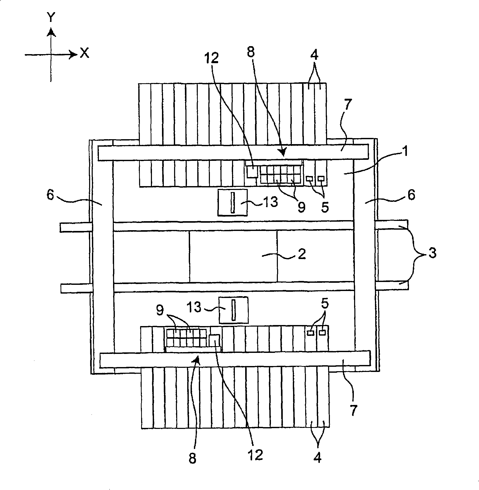
[0037] First, the whole structure of the electronic component mounting apparatus concerning embodiment of this invention is demonstrated. figure 1 A diagram showing the overall configuration of the electronic component mounting device according to the present embodiment, in figure 1 Among them, on the base 1 serving as a base of the electronic component mounting apparatus, a board conveying device 3 for conveying the board 2 is extended in the X direction. The board conveyance apparatus 3 has a function of sandwiching and holding the board|substrate 2, and functions as a board|substrate holding apparatus which holds the board|substrate 2 conveyed in the X direction at a predetermined position. In the present embodiment, the con...


PUM


Abstract

In electronic component mounting equipment, a nozzle mechanism is constituted by disposing a shaft type linear motor vertically above a nozzle unit and disposing a linear encoder vertically above the shaft type linear motor so that it has a slim shape. Consequently, occupied area of each nozzle mechanism can be reduced in the XY direction (horizontal direction), a pitch between adjoining nozzles can be made smaller, and a smaller mounting pitch in electronic components on a miniaturized, high-integration substrate can be dealt with.

Description

technical field [0001] The present invention relates to a nozzle mechanism, a mounting head, and an electronic component mounting device used for mounting of electronic components. Background technique [0002] With the progress of miniaturization, weight reduction, and high functionality of electronic equipment, further miniaturization and high integration are required for the substrates mounted thereon. In such a miniaturized and highly integrated substrate, since the pitch of the mounting portion where electronic components are mounted is narrowed, the mounting head is also required to have a narrower nozzle pitch. [0003] At present, the nozzle provided on the mounting head is configured to be able to move up and down and to rotate the axis with respect to the substrate, and the rotational drive of the motor provided on the upper part of the nozzle is converted into the up and down motion of the nozzle by a drive transmission mechanism such as a ball screw or a nut (ref...

Claims


Application Information

Patent Timeline
IPC IPC(8): H05K13/04
CPCH05K13/0452H05K13/0413H05K13/041Y10T29/53174Y10T29/53178Y10T29/53191B65G47/91H05K13/04
Inventor 金井一宪佐保秀浩高田力河口悟史
Owner PANASONIC CORP
Why Eureka
Try Eureka