Filtering device and method for its manufacture

A technology of filtration and filter, applied in separation methods, chemical instruments and methods, filtration separation, etc., can solve the problem of rhythm reduction and achieve the effect of high color depth

Inactive Publication Date: 2009-04-22
MANN HUMMEL GMBH
View PDF4 Cites 2 Cited by
  • Summary
  • Abstract
  • Description
  • Claims
  • Application Information

AI Technical Summary

Problems solved by technology

In addition, the hot stamping method also leads to a slow pace in the manufacturing process, since the melted mark locations must first cool down

Method used


Image

  • Filtering device and method for its manufacture
  • Filtering device and method for its manufacture

Examples


Embodiment Construction

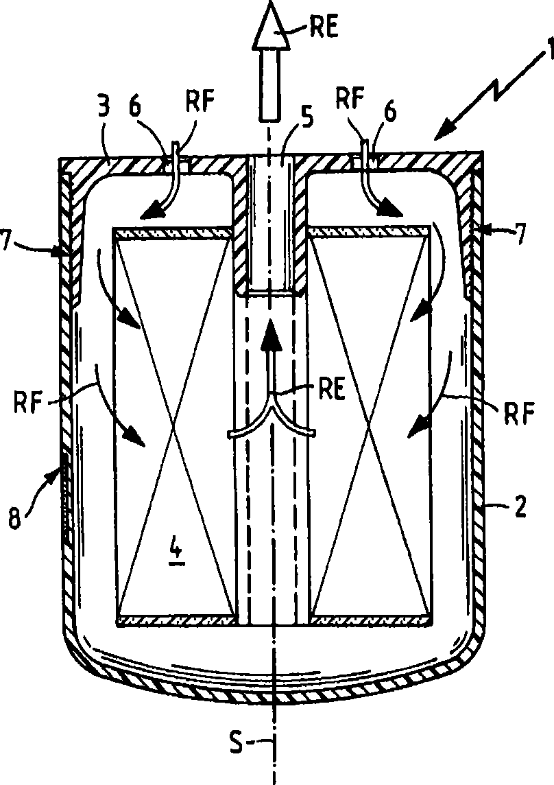
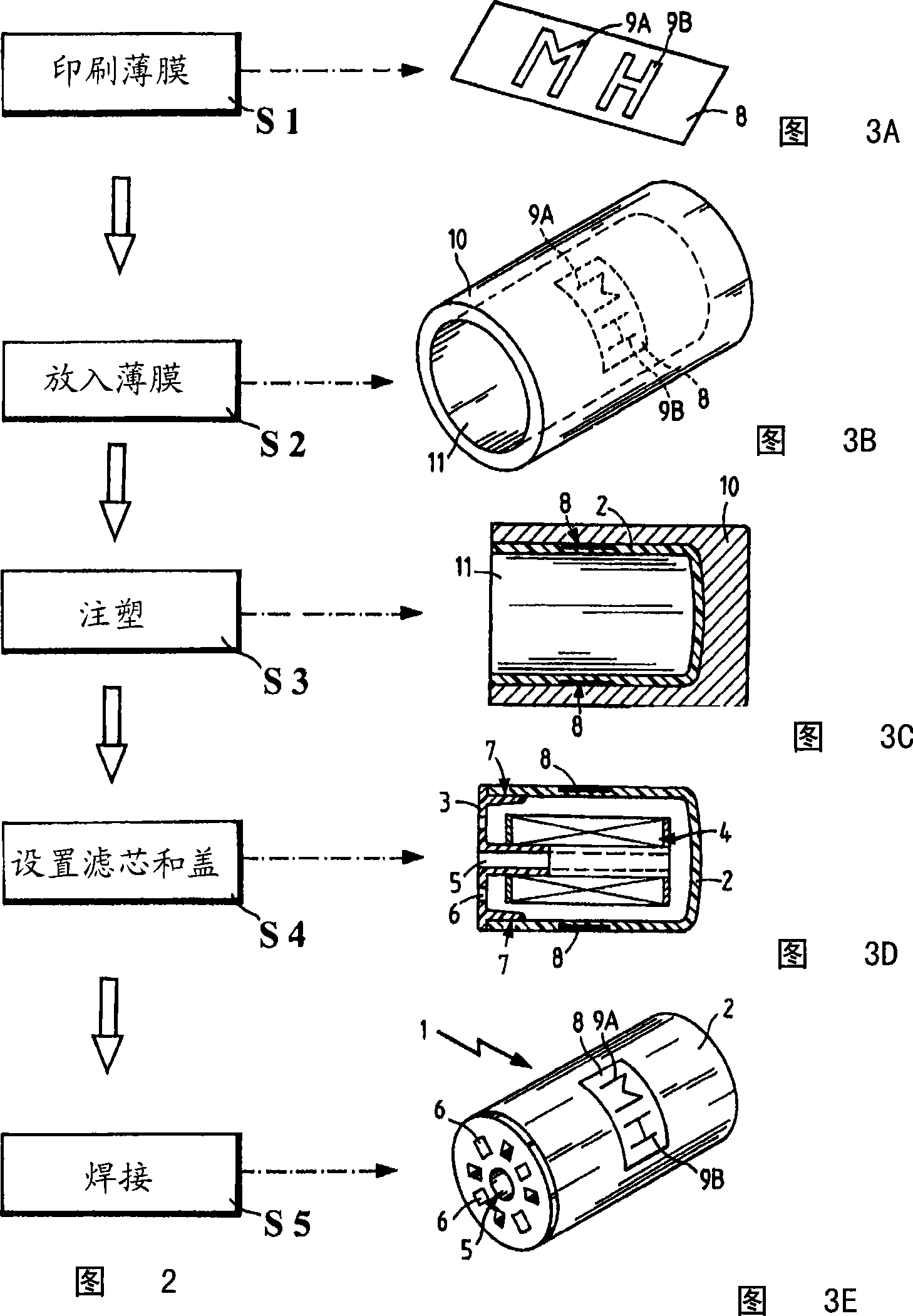
[0024] figure 1 A cross-sectional view of a filter device designed, for example, as an oil filter is shown. The filter device 1 has, for example, a cylindrical, open filter sump 2 in which a filter insert 4 is arranged.

[0025] The filter insert 4 can here be accordion-folded and have filter web material. In this case, the zigzag folded filter insert surrounds the axis of symmetry S, for example, and forms the interface between the raw fluid area and the cleaned fluid area in the filter sump 2 .

[0026] exist figure 1 In view from , the filter sump is closed upwards by the filter cover 3 . The filter cover 3 has a central opening 5 and further openings 6 through which raw fluid, for example motor oil, flows into the interior of the filter device 1 . This is shown by arrow RF. The oil to be filtered flows through the interface formed by the filter insert material and leaves the filter device 1 as cleaned fluid RE through the central opening 5 in the filter cover 3 . Flo...


PUM


Abstract

The invention relates to a filtering device and manufacturing method thereof. A filtering device (1) comprises a filter bottom shell (2) having plastic materials, filter cover (3) for closing the filter bottom shell (2), and a filtering element (4) set in the filter bottom shell (2), wherein the filter bottom shell (2) owns a mark face with at least one mark (9), the mark face is formed by using plastic film (8) with the mark (9) to do injection molding behind the film. A method for manufacturing filtering device composed of filter bottom shell (2), filter cover (3) and filtering element (4), wherein filter bottom shell (2) is formed by injection molding and provided with the mark face with the mark (9) formed behind the film by injection molding.

Description

technical field [0001] The invention relates to a filter device which can be used in particular as a replaceable plastic filter, for example an oil or fuel filter for a motor vehicle, and a method for producing a corresponding filter device. Replaceable filters are used, for example, for the filtration of fuel or lubricating oil in order to prevent the corresponding lubricating oil circuit from becoming muddy or from fouling the engine. Background technique [0002] A typical changeover oil filter consists of a solid metal housing or filter sump in which the filter element is located. Oil to be filtered enters through one or more concentric openings in the cover, flows through the filter element, and exits cleanly at an opening in the filter or filter pan. [0003] Therefore, it is desirable to manufacture corresponding replacement filters also from plastic material in order to save weight, which at the same time results in lower fuel consumption when used in motor vehicles...

Claims


Application Information

Patent Timeline
Patent Type & Authority Applications(China)
IPC IPC(8): B01D29/33B01D35/30B29C45/14B29L31/14
CPCB01D27/005B29C2045/14918B01D35/30B01D2201/52B29C2045/14713B29C45/14688B01D2201/50
Inventor A·克赖纳N·斯特拉森伯格B·巴克纳A·拉班特
Owner MANN HUMMEL GMBH
Why Eureka
Try Eureka