Material-pressing mechanism for angle-bar breaking mold and angle-bar breaking mold

A technology of angle steel and mold, applied in the field of pressing mechanism and angle steel punching mold, can solve the problems of poor verticality of end face axis, bulging and deflection of angle steel surface, etc.

Active Publication Date: 2009-04-22
CRRC QIQIHAR ROLLING CO LTD +1
View PDF1 Cites 18 Cited by
  • Summary
  • Abstract
  • Description
  • Claims
  • Application Information

AI Technical Summary

Problems solved by technology

However, because the angle steel punching die in the prior art does not provide a guide structure, the angle steel blank is prone to deflection during punching, and the perpendicularity between the end face and the axis of the angle steel is poor, so a large collapse angle is easily caused on the punching surface. There are quality defects such as drumming on the surface of the angle steel after punching

Method used


Image

  • Material-pressing mechanism for angle-bar breaking mold and angle-bar breaking mold
  • Material-pressing mechanism for angle-bar breaking mold and angle-bar breaking mold
  • Material-pressing mechanism for angle-bar breaking mold and angle-bar breaking mold

Examples


Embodiment Construction

[0026] In order to enable those skilled in the art to better understand the solution of the present invention, the present invention will be further described in detail below in conjunction with the accompanying drawings and specific embodiments.

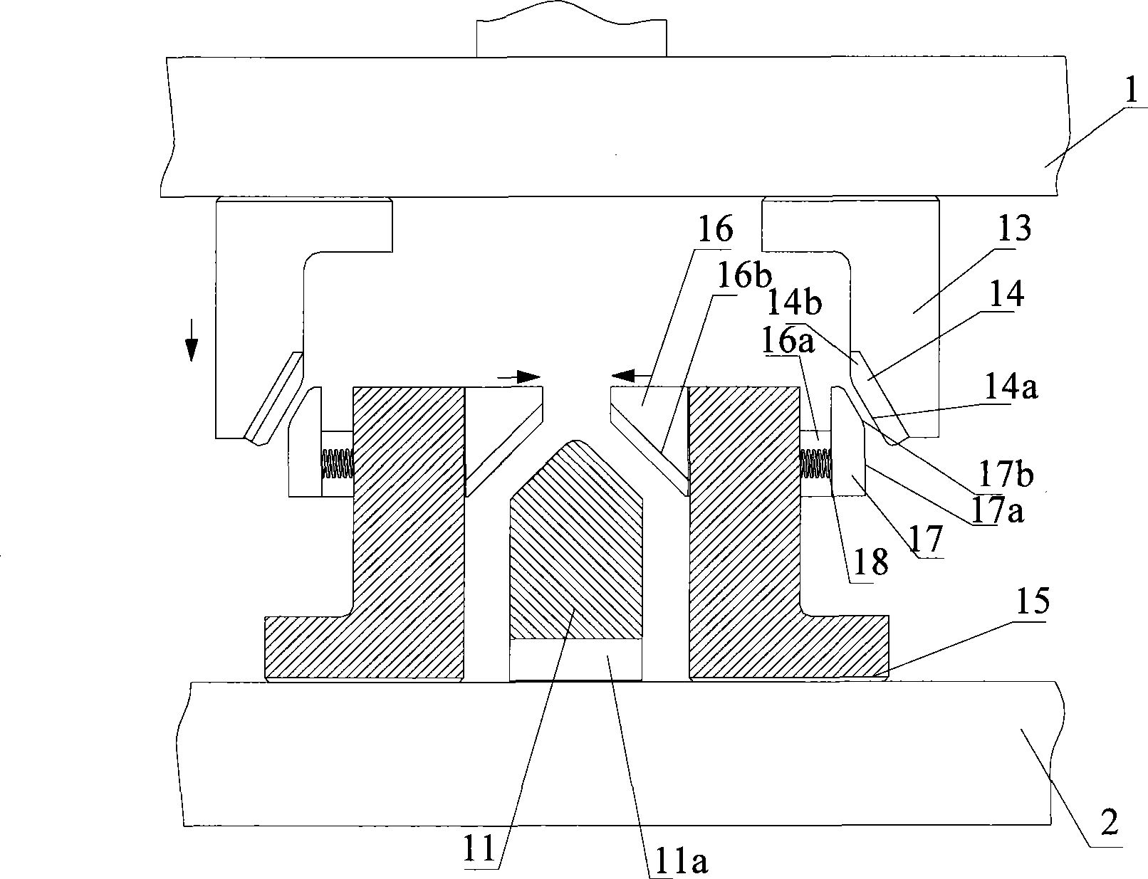
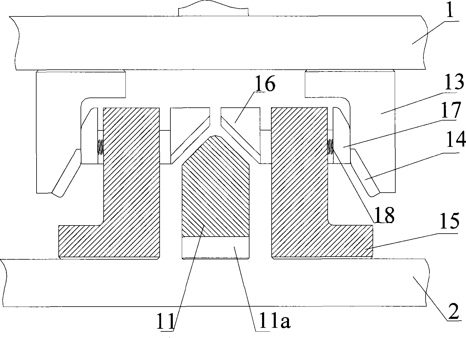
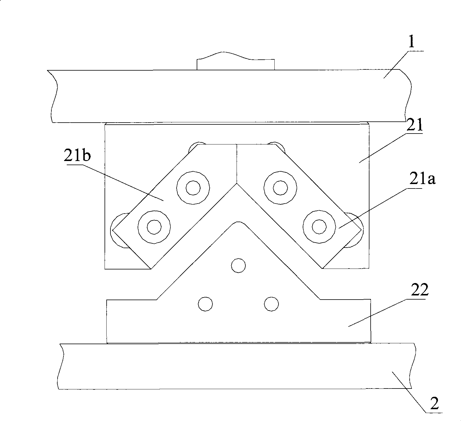
[0027] The mold for punching the angle steel provided by the present invention mainly includes two parts, the first part is the pressing mechanism part for positioning the workpiece, that is, the angle steel blank, and the second part is the punching structure part for punching the angle steel. The angle steel blank is positioned through the pressing structure. When punching, the angle steel is pressed by the pressing structure and the angle steel is cut by the punching structure. At the front and rear positions of the mould, a punching structure and a pressing structure are respectively installed.

[0028] like figure 1 and figure 2 As shown, it is a schematic diagram of the first specific embodiment of the pressing mechanism fo...


PUM


Abstract

The invention discloses a material clamping structure for an angle iron cutting die, which comprises a pair of clamping components which relatively slide to clamp two outer surfaces of an angle iron, a pair of clamping component brackets supporting the clamping components to slide and a material support base supporting the angle iron, wherein the material support base is arranged between the two clamping components; the material calmping structure also comprises a driving structure pushing the clamping components to relatively slide along the direction of the angle iron to clamp the angle iron and a resetting structure pushing the clamping components to slide away from the angle iron; according to the material clamping structure provided by the invention, the material support base has effects of supporting and piloting the angle iron blank material, by the relatively sliding clamping components clamping the two outer surfaces of the angle iron, the angle iron is prevented from inclination while the angle iron is cut, so the formation of a sunk angle on the cutting surface is avoided.

Description

technical field [0001] The invention relates to a punching die, in particular to a pressing mechanism for an angle steel punching die and an angle steel punching die. Background technique [0002] Angle steel is a common component used in construction industry, mechanical processing industry, transportation industry and other fields. According to different working occasions, the angle steel needs to be cut according to the set size when it is used. [0003] There are many ways to cut the angle steel. For example, the electric grinding wheel is used for high-speed rotary cutting, that is, the grinding wheel is installed on the grinder and rotated at a high speed under the drive of the motor. The angle steel is clamped on the grinding wheel frame, so that the outer edge of the grinding wheel is gradually approaching the angle steel. Make a cut. The disadvantage of this method is that the grinding wheel piece is worn out, the replacement is time-consuming and laborious, and t...

Claims


Application Information

Patent Timeline
Patent Type & Authority Applications(China)
IPC IPC(8): B21D28/02B21D28/14B23D33/02B23D35/00
Inventor 李信义王辉荣
Owner CRRC QIQIHAR ROLLING CO LTD
Why Eureka
Try Eureka