Recording medium and recording apparatus

一种记录介质、记录装置的技术,应用在打印装置、印刷、打字机等方向,能够解决成本高、不能提高记录位置精度等问题

Inactive Publication Date: 2009-04-22
SEIKO EPSON CORP
View PDF2 Cites 2 Cited by
  • Summary
  • Abstract
  • Description
  • Claims
  • Application Information

AI Technical Summary

Problems solved by technology

[0005] However, in the case of using the device of Patent Document 1, there is a problem that a sensor needs to be provided, resulting in high cost.
In addition, in the case of using the device of Patent Document 2, although the position deviation of the recording medium relative to the transport tray can be prevented, if the transport tray is transported in a state inclined to the transport direction, the accuracy of the recording position cannot be improved.

Method used


Image

  • Recording medium and recording apparatus
  • Recording medium and recording apparatus
  • Recording medium and recording apparatus

Examples


no. 1 Embodiment approach

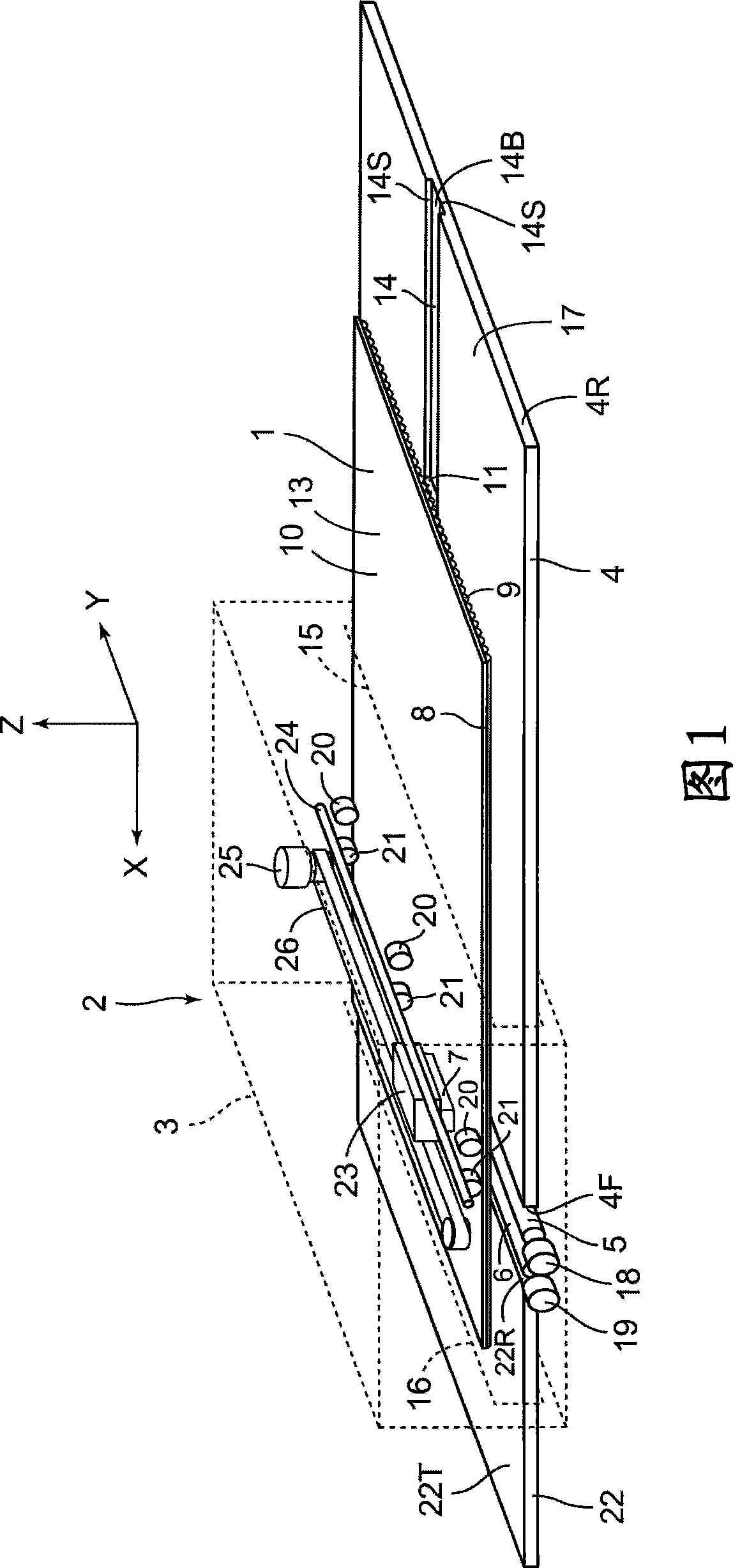
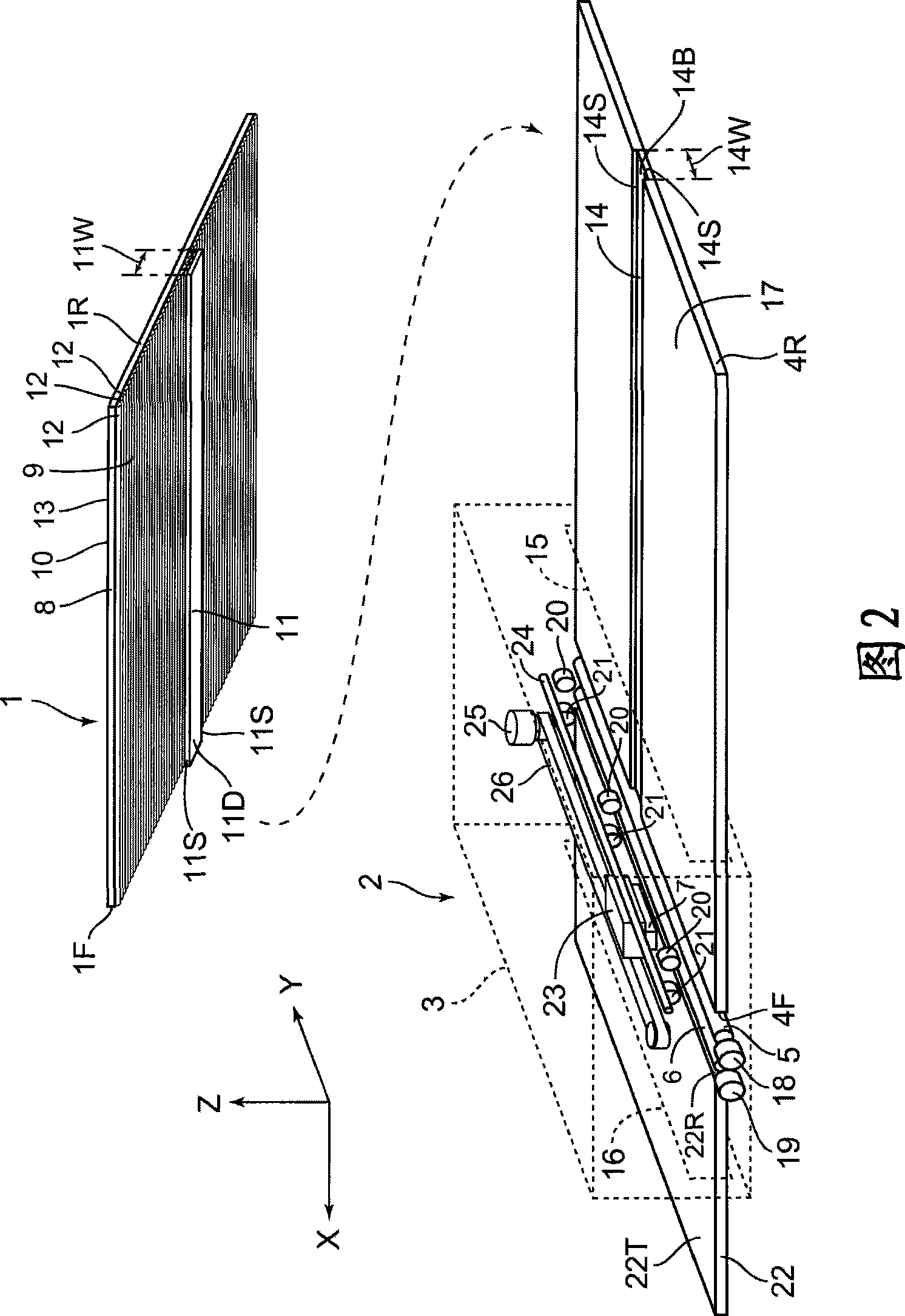
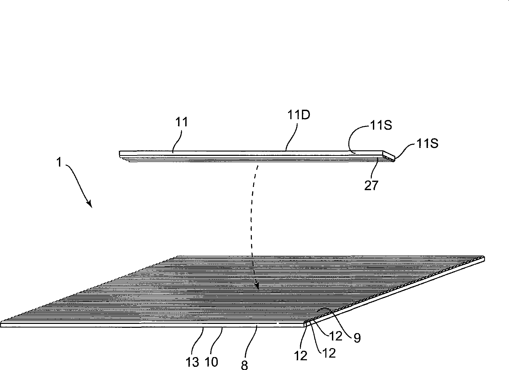
[0042] Below, refer to Figure 1 to image 3 , the lens sheet 1 and the recording device 2 according to the first embodiment of the present invention will be described.

[0043] 1 is a schematic configuration diagram showing a schematic configuration of a recording device 2 in a state where a lens sheet 1 as a recording medium is incorporated, and is a perspective view of the recording device 2 viewed from the rear. FIG. 2 is a diagram showing a state where the lens sheet 1 is detached from the recording device 2 shown in FIG. 1 . image 3 It is an exploded perspective view showing the structure of the lens sheet 1 . In addition, in the following description, in FIGS. 1 and 2 , the direction in which the lens sheet 1 travels, that is, the direction of arrow X is referred to as the front (front side), and the opposite direction is referred to as the rear (rear side). Furthermore, the direction of the arrow Y that is the right-hand direction from the rear to the front is referred...

Deformed example 4

[0083] (Modification 4 of lens sheet, Modification 2 of recording device)

[0084] FIG. 8 shows the structures of a lens sheet 70 as a fourth embodiment of the lens sheet 1 and a recording device 71 as a second modified example of the recording device 2 . In addition, about the same structure as demonstrated in the said 1st Embodiment, the same code|symbol is attached|subjected, and description is abbreviate|omitted.

[0085] As shown in FIG. 8 , the lens sheet 70 is provided with ridges 72 having the same structure as the ridges 11 on the left and right. Further, the sheet guide member 73 is provided with guide grooves 74 having the same structure as the above-described guide groove 14 on the left and right corresponding to the protruding line portion 72 . In addition, the recording device 71 has the same configuration as the above-described recording device 2 except for the configuration of the sheet guide member 73 . As described above, by guiding the lens sheet 70 at two...

no. 2 Embodiment approach

[0087] Below, refer to Figure 9 , the configuration of the lens sheet 80 according to the second embodiment of the present invention will be described. In addition, the same reference numerals are assigned to the same configurations as those described in the above-mentioned first embodiment and its modifications, and description thereof will be omitted.

[0088] The lens sheet 80 is provided with a recording area 81 and a convex portion installation area 82 located on the left and right outer sides of the recording area 81 . In this convex portion installation area 82, a lenticular lens 9 is provided in the same manner as the recording area 81, and is integrally formed with the recording area 81, but a perforated hole 83 as a cut-off structure is formed in the front-rear direction between the two. . Therefore, the convex-line portion installation region 82 can be cut out from the recording region 81 . Also, by forming a V-shaped groove instead of the perforation 83 , it is...


PUM


Abstract

The invention provides a recording medium and recording apparatus which can improve an accuracy of a recording position with a simple configuration. A recording medium(a lens sheet 1 with a double-convex lens 3) includes a guided portion (a raised strip 11) guided by a guide portion(a guide groove 14) which is provided in a supporter (a sheet guide 4) for supporting the recording medium (the lens sheet 1) provided on a recording apparatus 2 carrying out a recording on the recording medium, so that the recording medium (the lens sheet 1) is guided in a predetermined conveying direction.

Description

technical field [0001] The present invention relates to a recording medium having a lenticular lens and a recording device capable of recording on the recording medium. Background technique [0002] In the past, there is known a recording medium as follows, which has a lenticular lens superimposed on the recording layer, and the image recorded on the recording layer can be observed as a stereoscopic image through the lenticular lens, or can be seen due to different viewing angles. A change image in which the shape of the image etc. changes. In order to observe the image recorded on the above-mentioned recording medium as a predetermined stereoscopic image or a changing image, it is necessary to accurately correspond the recording position on the recording layer to the lens arrangement of the lenticular lens. Therefore, for example, Patent Document 1 discloses a device that detects the position of a lenticular lens using a sensor, and performs recording at a desired position...

Claims


Application Information

Patent Timeline
Patent Type & Authority Applications(China)
IPC IPC(8): B41J3/407B41J13/10
CPCB41J13/14B41J3/407B41J11/06
Inventor 铃木胜仁
Owner SEIKO EPSON CORP
Why Eureka
Try Eureka